The catalyst for the creation of MoFEM was the need for a flexible and numerically accurate modelling environment for multi-physics problems posed by our partners, including industry (EDF Energy, Jacobs, Advanced Forming Research Centre (University of Strathclyde), Rolls-Royce, etc).
MoFEM delivers a software development platform which enhances scientific innovation by providing a flexible and adaptable modelling framework, using novel disruptive approaches to long-standing problems in continuum mechanics and tackling conflicting requirements of accuracy and computational efficiency. This is achieved in MoFEM by developing and adopting state-of-the-art FE technologies, for example: \(H^1\)-, \(H(\text{curl})\)-, \(H(\text{div}\))- and \(L^2\)-conforming finite elements equipped with hierarchical, heterogeneous and anisotropic approximation bases; error-driven hp-adaptivity; mesh topology evolution. In addition, MoFEM’s HPC capabilities are supported by its unique data structures that are capable of handling generic multi-field, multi-physics, multi-scale problems and building tailored composite solvers.
Therefore, MoFEM provides users with an effective tool for solving Partial Differential Equations arising in various fields of Engineering and Applied Physics: solid mechanics, fluid mechanics, soft matter physics, heat transfer, electromagnetism, etc. Furthermore, MoFEM features an extendable modular design: while its open-source core library is developed to manage the complexities of FEM, additional user modules are devoted to particular applications. Such a toolkit-like structure allows for independent development of modules with different repositories, owners and licenses.
Figure: (a) Scalability of the block preconditioner with algebraic multigrid for shallow wave equation, (b) Parallel partitions and (c) solution of shallow wave equation on the surface of Earth
Solid mechanics problems
Brittle crack propagation under contact loading
\(\textbf{I. Athanasiadis}^1, \textbf{A. G. Shvarts}^1, \textbf{Ł. Kaczmarczyk}^1,\textbf{K. Lewandowski}^1, \textbf{C. Pearce}^1\)
\(^1 \textit{Glasgow Computational Engineering Centre, James Watt School of Engineering, University of Glasgow}\)
We present the first implicit computational framework for simulating crack propagation along contact interfaces and surfaces under load in three-dimensional bodies. We restrict ourselves to brittle fracture and frictionless contact and focus on numerical challenges associated with the coupling of unilateral constraints emerging from the Griffith's criterion and the contact conditions. The formulation is based on the configurational mechanics framework and is solved using the finite element method. The approach utilises a monolithic Arbitrary Lagrangian-Eulerian formulation permitting simultaneous resolution of crack propagation and unilateral contact constraints. Contact is embedded in the model using the well-known mortar contact formulation. Evolving cracks are explicitly modelled as displacement discontinuities within the mesh. Heterogeneous approximation of arbitrary order is used to discretise spatial displacements, enabling \(hp\)-adaptive refinement around the crack front and the contact interfaces traversed by the crack. The result is a holistic approach which handles issues associated with thermodynamic consistency, numerical accuracy and robustness of the computational scheme. Several numerical examples are presented to verify the model formulation and implementation; they also highlight how contact pressure and load applied on surfaces traversed by cracks influence their propagation. The robustness of the approach is validated by comparison of our simulations with industrial experiment involving cracks of complex morphologies propagating along contact interfaces between multiple deformable bodies
[8].
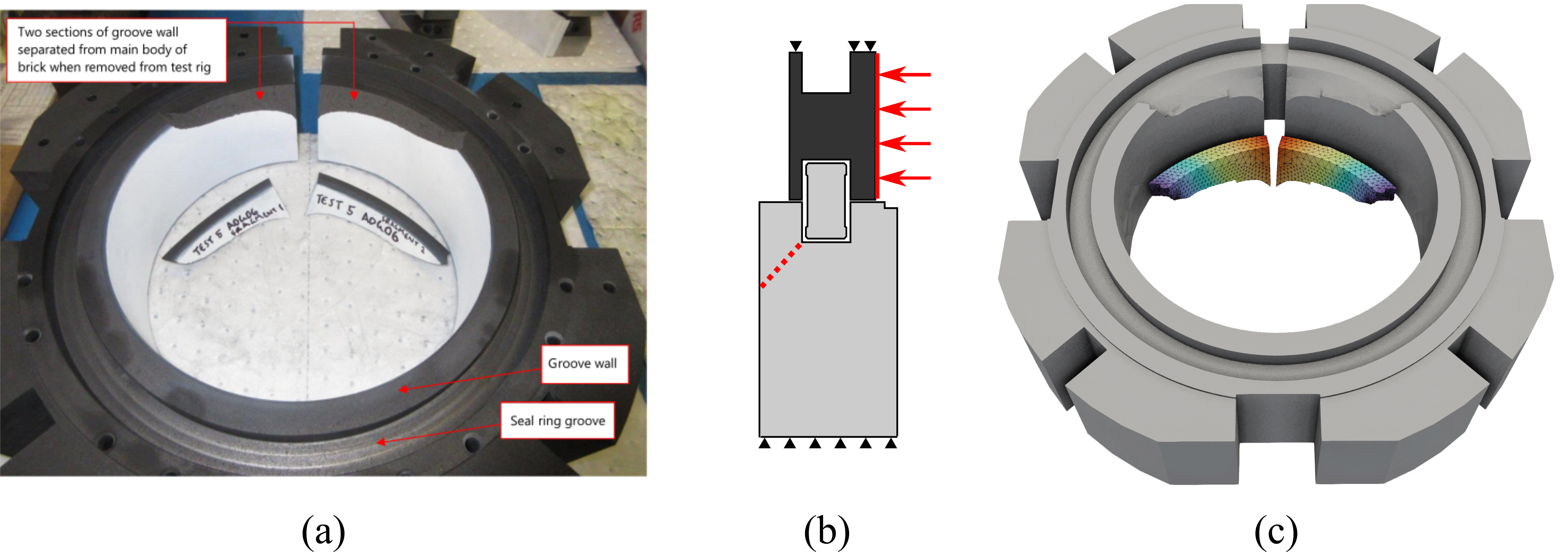
Figure: (a) experimental results for crack propagation in the graphite brick slice caused by contact with the graphite seal ring and the steel loading collar (not shown), (b) schematic side view showing the brick slice, the seal ring and the loading collar, (c) results of the simulation [8]
Simulation-augmented atomic force microscopy of cells
\(\textbf{Andrei G. Shvarts}^{1}, \textbf{Giuseppe Ciccone}^{2}, \textbf{Łukasz Kaczmarczyk}^{1}, \textbf{Massimo Vassalli}^{2}\)
\(^1 \textit{Glasgow Computational Engineering Centre, James Watt School of Engineering, University of Glasgow}\) \(^{2}\textit {Centre for the Cellular Microenvironment, James Watt School of Engineering, University of Glasgow} \)
Mechanobiology is an emerging multidisciplinary field at the crossroads of medicine, biology, physics and engineering. It focusses on how physical forces drive pathophysiological processes from the cell to the tissue level scale
[42]. A key role in understanding of these processes is attributed to mechanical properties of cells. The state-of-the-art approach for identification of elastic properties of cells is based on nanoindentation experiments exploiting atomic force microscopy (AFM). While these experiments provide wealth of information on the elastic response of cells, the current analysis is often limited to fitting using analytical contact mechanics models based on the assumption that cells can be treated as homogeneous isotropic linear elastic solids. However, much more can be learned from single cell nanoindentation by augmenting experimental procedures with numerical simulation, for example, by using the finite-element method considering heterogeneous solids and nonlinear behaviours. Our objective is to provide an increase in the detail and reliability of extracted mechanical data from AFM experiments by developing an experimentally-informed numerical model of the nanoindentation process. We consider hyperelastic and viscoelastic materials undergoing large deformations, while the contact interaction is handled by consistent and stable numerical algorithms. This permits to extract mechanical properties of cells from experimental data with high precision, setting a new standard in the analysis of nanoindentation curves.
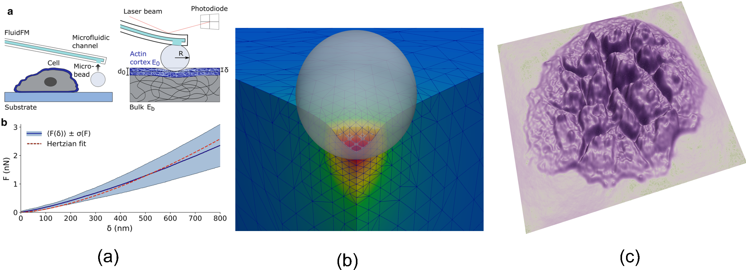
Figure: (a) Sketch of the experimental setup; (b) force-indentation data fitting [49] (b) finite-element simulation of cell nanoindentation using hyperelastic neo-Hookean material model (c) Cell layer's surface roughness reconstructed using finite-element solution of the transport-of-intensity equation
Multifield finite strain plasticity: Theory and numerics
\(\textbf{Karol Lewandowski}^{1}, \textbf{Daniele Barbera}^{2}, \textbf{Callum J. Runcie}^{1}, \textbf{Ross Williams}^{1}, \textbf{Andrew McBride}^{1}, \textbf{Paul Steinmann}^{1,3}, \textbf{Chris Pearce}^{1},\\ \textbf{Lukasz Kaczmarczyk}^{1}\)
\(^{1} \textit{Glasgow Computational Engineering Centre, James Watt School of Engineering, University of Glasgow}\) \(^{2} \textit {Advanced Forming Research Centre, University of Strathclyde} \) \(^{3} \textit{Chair of Applied Mechanics, Friedrich-Alexander University Erlangen-Nürnberg}\)
The development of a massively parallel multifield plasticity formulation for finite strain plasticity
[45] is motivated by the inability of classical computational plasticity to fully exploit modern scientific computing, due to internal variables, problematic in case of advection in an Arbitrary Lagrangian Eulerian formulation. To avoid the local integration of the elastoplastic material model, the balance of linear momentum, the flow relation, and the Karush–Kuhn–Tucker constraints are collectively cast in a variational format.
An additive kinematic split, proposed by Miehe et al
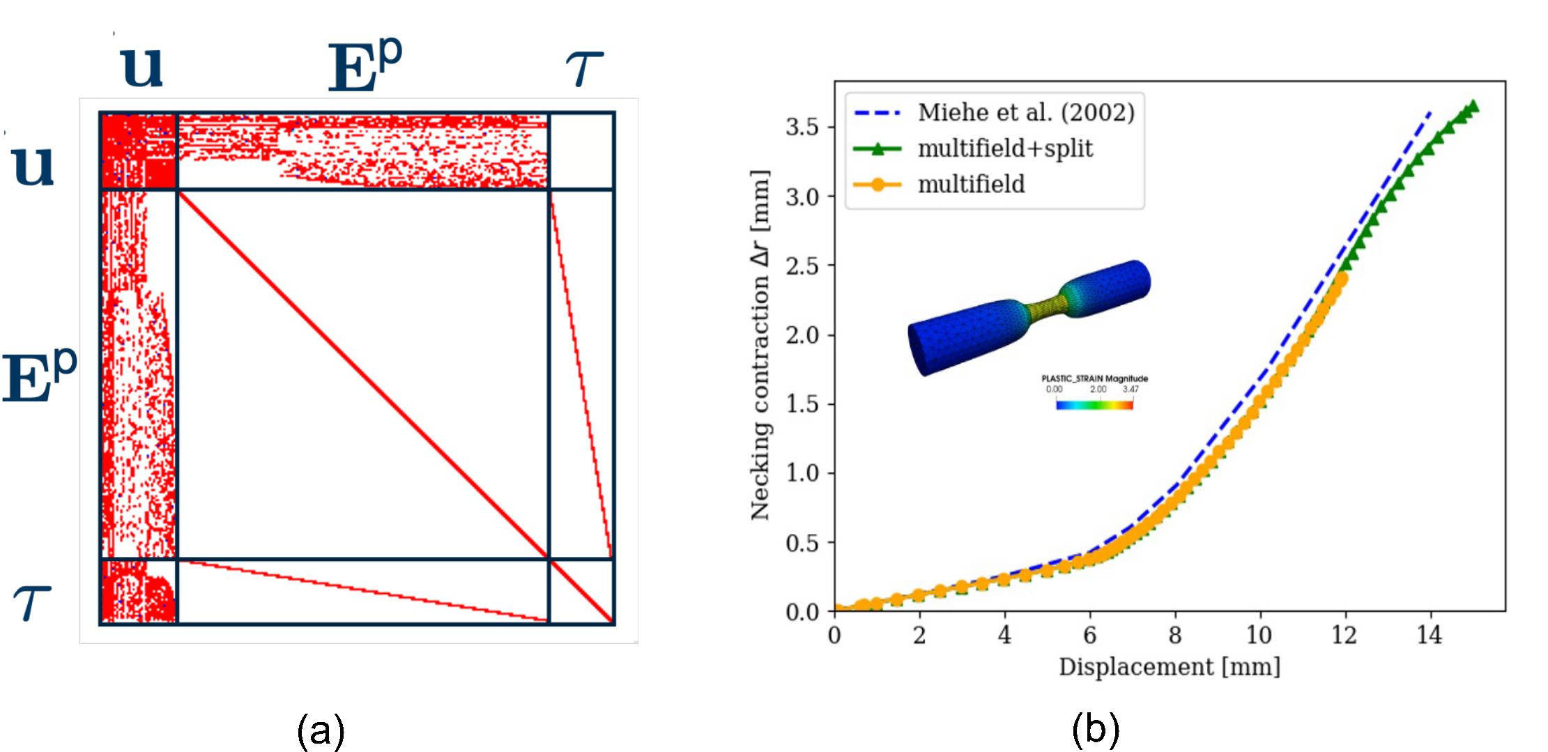
[54], facilitates the expression of finite strain models in a classical small strain setting by introducing a logarithmic strain measure. The measures of plastic deformation are directly approximated using finite element basis functions in \(L^2\) space. The ensuing proliferation of global degrees of freedom is addressed by exploiting the block sparse structure of the algebraic system together with a tailored efficient and scalable block matrix solver which can utilise emerging hardware architectures.
The problem is solved implicitly on a global level with a monolithic Newton-Raphson scheme. The flexible approach allows for straightforward coupling with physical phenomena such as contact mechanics and thermally-driven material behaviours. A series of numerical problems in fig. (b) demonstrate the validity, capability, and efficiency of the proposed approach.
Figure: (a) Block structure of the resulting linear system (b) Necking benchmark results comparison
A mixed Finite Element method for 3D elasticity problems at large strains with weakly imposed symmetry
\(\textbf{C-A. Chalons-Mouriesse}^{1}, \textbf{Lukasz Kaczmarczyk}^{1}, \textbf{Chris Pearce}^{1}\)
\(^1 \textit{Glasgow Computational Engineering Centre, James Watt School of Engineering, University of Glasgow}\)
We show an extension of the mixed finite element for small strain elasticity to large strain problems. This work develops finite element formulation, where are independently approximated four fields, i.e. stresses, logarithm stretches, rotations vector, and displacements. Each field is associated with sets of equations, i.e. conservation of linear momentum, conservation of angular momentum, constitutive equation, and consistency equation between displacements and deformation. The connection between rotations vector and rotation tensor is established by exponential map. The stresses are approximate in \(H(\text{div})\) space, and remaining three fields in \(L^2\) space. Such formulation creates a very sparse system of equations, easy to parallelise, enabling highly-scalable and robust solvers. The finite element is implemented in open-source software, MoFEM
[39], developed at the Glasgow Computational Engineering Centre. This novel finite element technology enables us to tackle problems nearly incompressible soft materials. Also, finite element mixed-formulation opens new possibilities to tackle robust problems in DD-driven approaches for large strains and multi-field formulations for computational plasticity and efficient error estimators for \(p\)-adaptivity.
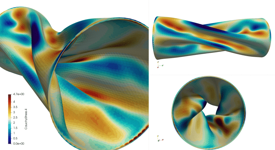
Figure: Deformation of nearly incompressible tube under rotation
A stable formulation of Lagrange multipliers for enforcing contact constraints using arbitrary orders of approximation
\(\textbf{I. Athanasiadis}^{1}, \textbf{A. Shvarts}^{1}, \textbf{K. Lewandowski}^{1}, \textbf{C. J. Runcie}^{1}, \textbf{R. Williams}^{1}, \textbf{A. McBride}^{1}, \textbf{P. Steinmann}^{1, 2}, \textbf{C. Pearce}^{1},\\ \textbf{L. Kaczmarczyk}^{1}\)
\(^1 \textit{Glasgow Computational Engineering Centre, James Watt School of Engineering, University of Glasgow}\) \(^2 \textit{Chair of Applied Mechanics, Friedrich-Alexander University Erlangen-Nürnberg}\)
This work focuses on 3D modelling of contact between rigid and elasto-plastic bodies within the Finite Element (FE) framework using the Lagrange Multipliers (LM) approach to fulfill Karush-Kuhn-Tucker (KKT) conditions. The dual base proposed in
[33] and successfully used for large strains
[57] to approximate the LM field is in the appropriate energy space \(H^{-1/2}\) and can be explicitly used for \(h\)-refinement. However, for \(p\)-refinement a new approach must be proposed to take advantage of inherent benefits of heterogeneous basis functions such as compatibility with optimal multi-grid solvers. We present a novel approach for modelling contact problems, where the discrete functional space for LM defined on contact surfaces emerges from the trace of Raviart-Thomas space defined inside the domain. This approach enables to evaluate terms present in contact formulation both on the boundary and within the volume via Gauss theorem, providing stability to the discrete solution. Furthermore, it allows for higher-order approximation, permitting to combine \(h\)-refinement with \(p\)-refinement. The framework was successfully used for modelling Incremental Cold Flow Forming (ICFF) and flat tyre rolling on a rigid flat surface. The framework will be extended to model contact between two flexible bodies for elastic and crack propagation conditions.

Figure: Examples of implementation of the proposed contact model for arbitrary orders of approximation: (a) ICFF and (b) flat tire
An industry driven approach to numerical modelling of the Incremental Cold Flow Forming process
\(\textbf{Callum J. Runcie}^{1}, \textbf{Karol Lewandowski}^{1}, \textbf{Daniele Barbera}^{1}, \textbf{Andrew McBride}^{1}, \textbf{Paul Steinmann}^{1, 2}, \textbf{Chris Pearce}^{1},\\ \textbf{Lukasz Kaczmarczyk}^{1}\)
\(^1 \textit{Glasgow Computational Engineering Centre, James Watt School of Engineering, University of Glasgow}\) \(^2 \textit{Chair of Applied Mechanics, Friedrich-Alexander University Erlangen-Nürnberg}\)
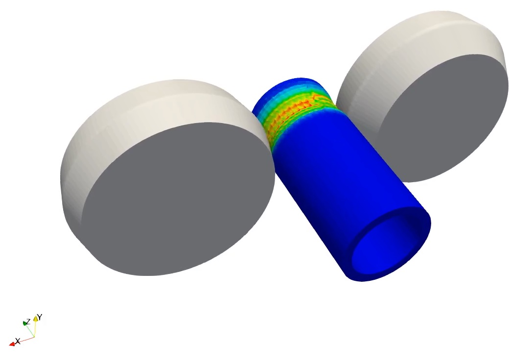
In the last two decades, incremental cold flow forming (ICFF) has progressively advanced as a metal forming process. The design of this process is inherently difficult and still poorly understood, due to complex underlying physical phenomena involving hollow cylindrical geometry, undergoing fast rotational rigid body contact loading, resulting in large plastic deformations. Commercially available finite element packages are currently providing unreliable and computationally expensive solutions in an attempt to understand the process. To address these challenges, a multifield approach to plasticity was developed in MoFEM by the co-authors
[45]. This approach is highly flexible, allowing for straightforward coupling with other physical phenomena including contact mechanics and advection of the plastic variables as part of an Arbitrary Lagrangian Eulerian (ALE) formulation improving the overall robustness of the numerical scheme for modelling ICFF.
Furthermore, to aid engineers in understanding the manufacturing process, the ability to modify and adjust the rigid indenter geometry and movement paths easily are a top priority to investigate different process setups quickly and efficiently, such as those shown in the following Figure. Therefore a simple python interface was developed in MoFEM to allow any user to easily implement custom rigid body geometry or a movement path through a signed distance function (SDF). A SDF is used to define the location of a surface and when provided a set of coordinates it returns either a positive value (gap) to the rigid surface, a negative value (penetration) or zero when on the surface itself. This can easily be adopted into any contact formulation in order to resolve the classical KKT contact conditions.
Figure: Contact of rigid rollers with rotating elasto-plastic workpiece
Transport problems
A p-adaptive, implicit-explicit mixed finite element method for diffusion-reaction problems
\(\textbf{Mebratu Wakeni}^{1}, \textbf{Ankush Aggarwal}^{1}, \textbf{Lukasz Kaczmarczyk}^{1}, \textbf{Andrew McBride}^{1}, \textbf{Paul Steinmann}^{1,2}\)
\(^1 \textit{Glasgow Computational Engineering Centre, James Watt School of Engineering, University of Glasgow}\) \(^2 \textit{Chair of Applied Mechanics, Friedrich-Alexander University Erlangen-Nürnberg}\)
A new class of implicit-explicit methods combined with a p-adaptive mixed finite element formulation is proposed to simulate the diffusion of reacting species in MoFEM. Hierarchical polynomial functions are used to construct a conforming base for the flux vectors, and a non-conforming base for the mass concentration of the species. The mixed formulation captures the distinct nonlinearities associated with the flux constitutive equations and the reaction terms. The IMEX method conveniently treats these two sources of nonlinearity implicitly and explicitly, respectively, within a single time-stepping framework. A reliable a posteriori error estimate is proposed and analysed. A p-adaptive algorithm based on the proposed a posteriori error estimate is also constructed. The combination of the p-adaptive mixed formulation and the IMEX method delivers a robust and efficient algorithm. The proposed methods eliminate the coupled effect of mesh size and time step duration on the algorithmic stability. A residual-based a posteriori error estimate is derived, and when combined with the hierarchical finite element spaces allow for the formulation of an efficient p-adaptive algorithm
[76] . A series of numerical examples demonstrate the performance of the approach for problems involving travelling waves, and possessing discontinuities and singularities.
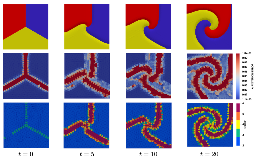
Figure: Development of a spiral pattern as a result of cyclic interactions of three species. Observe adapting heterogeneous approximation order at time steps
Weaker mixed finite element formulation for data-driven approach
\(\textbf{Adriana Kuliková}^{1}, \textbf{Andrei G. Shvarts}^{1}, \textbf{Lukasz Kaczmarczyk}^{1}, \textbf{Chris Pearce}^{1}\)
\(^1 \textit{Glasgow Computational Engineering Centre, James Watt School of Engineering, University of Glasgow}\)
The standard approach to mechanical problems requires the solution to the mathematical equations that describe both the conservation laws and the constitutive relationships, where the latter are obtained after fitting experimental data to a certain material model. Such models range from simple linear constitutive relationships with just one constant (e.g. Darcy's law for saturated flow) to more complex ones, such as unsaturated flow, hyperelasticity, brittle fracture of heterogeneous materials, requiring fitting of multiple parameters.
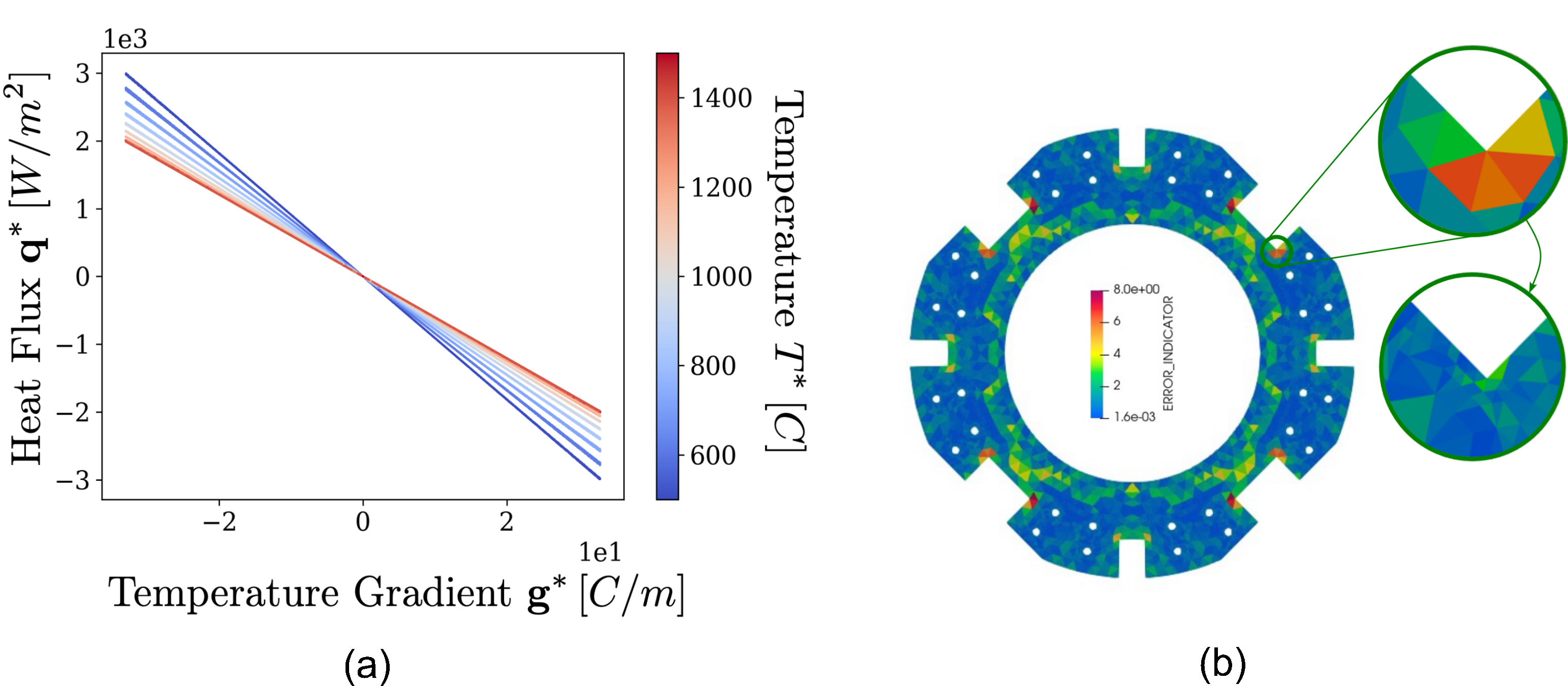
In this work, we follow the data-driven (DD) approach
[40] as an alternative to material modeling, and develop a DD finite element framework for nonlinear diffusion problems, such as heat transfer in porous media. In particular, we consider nuclear graphite which has nonlinear dependence of the heat flux on temperature and its gradient resulting from the irradiated graphite microstructure. DD approach allows to avoid any empirical material models by using the experimental material data directly in the numerical simulations as well as to access uncertainty of the solution propagating from the noisy material dataset
[43] .
To satisfy the conservation laws and boundary conditions, we use a finite element method applied to a weaker mixed formulation
[14] that enforces normal flux continuity across inner boundaries. This formulation provides \textit{a posteriori} error estimates that enable adaptive refinement, as shown in figure, reducing the number of unknowns required to achieve the desired accuracy and minimizing the number of searches through the material dataset.
Figure: (a) Material dataset generated by synthetic experiments with nonlinear thermal conductivity (b) Adaptive mesh refinement in finite elements highlighted by a posteriori error indicator enabled by weaker mixed formulation
Numerical simulation of photon diffusion through highly disperse media for optical imaging applications
\(\textbf{Andrei G. Shvarts}^{1}, \textbf{Lukasz Kaczmarczyk}^{1}, \textbf{Jack Radford}^{2}, \textbf{Samuel L. Nerenberg}^{2}, \textbf{Daniele Faccio}^{2}\)
\(^1 \textit{Glasgow Computational Engineering Centre, James Watt School of Engineering, University of Glasgow}\) \(^2 \textit{Extreme Light Group, School of Physics and Astronomy, University of Glasgow}\)
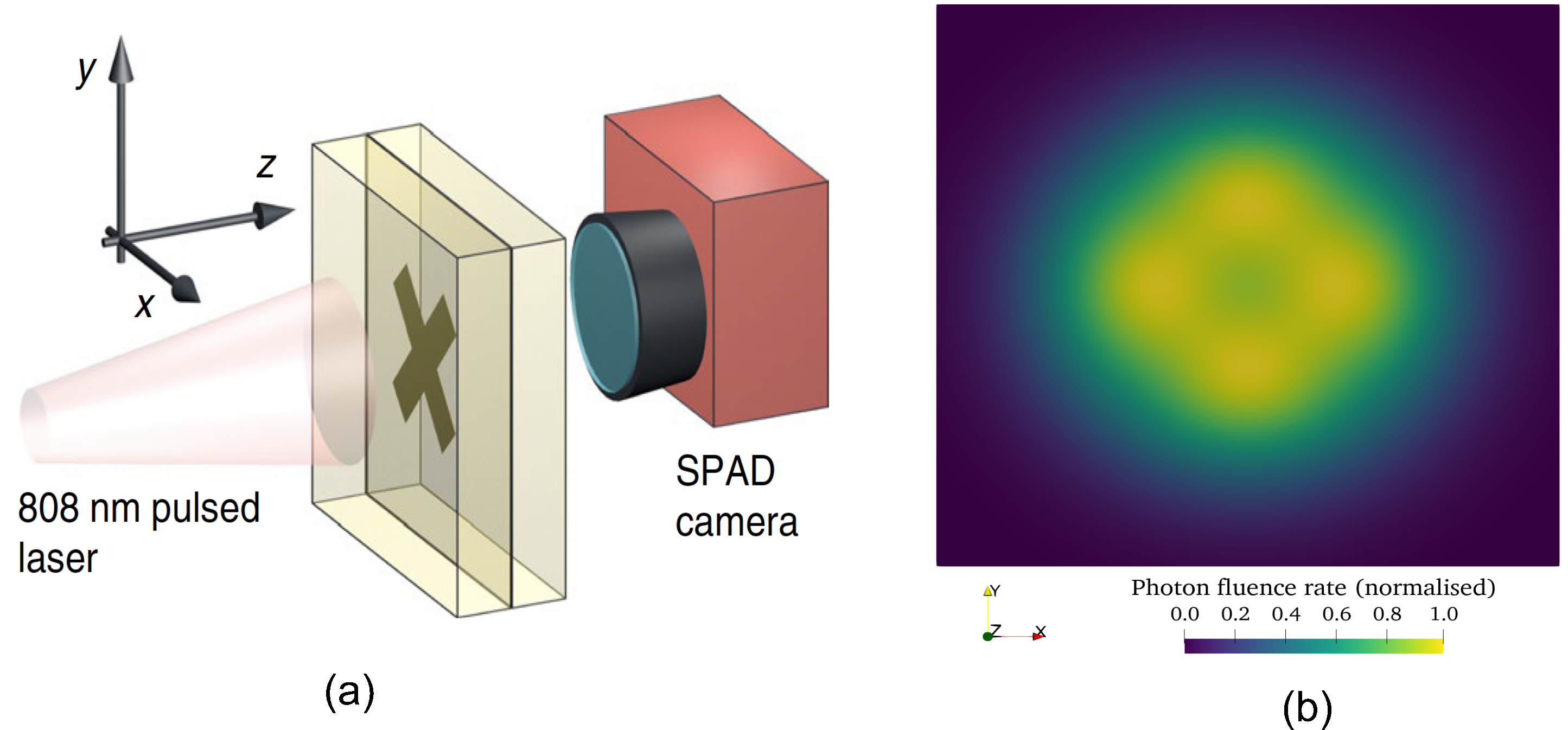
Our colleagues at the Extreme Light research group at the University of Glasgow are working on optical imaging through highly disperse (scattering) media for biological and health applications
[51],
[58]. In particular, the Bayesian Neural Network (BNN) are used to reconstruct images of hidden objects
[70] , however, experiments are time consuming, and do not provide necessary number of data sets for training of BNN. A possible solution to this problem is to simulate numerically photon transmission through the scattering medium.
Since the photon diffusion equation has the same differential operator as the classic diffusion equation, the spatial and temporal distribution of the photon flux can be obtained using MoFEM's functionality. Therefore, MoFEM provides a reliable, robust and fast tool which enriches the analysis methodology and improves the quality of BNN predictions
[59] . The next step of the project is modelling of photon transmission through human organs, e.g. brain, the geometry of which can be built based on MRI scans. This study will help to understand, validate and test the feasibility of the optical imaging technique.
Figure: (a) Experimental setup for diffuse optical imaging of hidden objects (b) Image of a hidden object obtained by numerical simulation of photon diffusion
Multiphysics problems
Computational framework for simulation of triboelectric nanogenerators accounting for surface roughness
\(\textbf{Andrei G. Shvarts}^{1}, \textbf{Charchit Kumar}^{2}, \textbf{MD Tanzib E. Sanglap}^{1}, \textbf{Ignatios Athanasiadis}^{1}, \textbf{Lukasz Kaczmarczyk}^{1}, \textbf{Daniel M. Mulvihill}^{2},\\ \textbf{Chris Pearce}^{1}\)
\(^1 \textit{Glasgow Computational Engineering Centre, James Watt School of Engineering, University of Glasgow}\) \(^2 \textit{Materials and Manufacturing Research Group, James Watt School of Engineering, University of Glasgow}\)
Triboelectric nanogenerators (TENG) transform mechanical energy into electrical energy as a result of contact between suitably chosen surfaces
[78]. Surface roughness plays a key role in their performance, defining the extent of the real contact area. In this study we develop a novel approach for coupling mechanical contact and electrostatics equations, permitting simulation of TENG with representative surface roughness.
For a given contact force and measured surface roughness data, the simulation is performed in two stages
[65]. In the contact stage, we solve the contact problem between a dielectric solid (with effective roughness and elastic properties) and a rigid flat. The solution of this problem provides the real contact area morphology which defines the location of surface tribo-charges. In the separation stage, we solve the electrostatics problem in the domain consisting of both dielectric layers and the air gap and compute the open-circuit voltage.
The obtained results show good agreement with both experimental observations and a simplified analytical solution
[78]. At the same time, the developed coupled finite-element framework permits extensions accounting for non-linear (e.g. elastoplastic) material behaviour of dielectric layers and/or interfacial friction during the contact stage. Moreover, the proposed framework allows to consider heterogeneous materials and predict the effect of inclusions in the dielectric layers, facilitating the optimization and design of new TENG.
Figure: (a) FEM modeling of TENG with rough surface: contact stage, (b) Evolution of the open-circuit voltage under increasing external load
Modelling of macrosegregation during steel ingot casting
\(\textbf{Richard Olley}^{1}, \textbf{Ignatios Athanasiadis}^{1}, \textbf{Andrei Shvarts}^{1}, \textbf{Lukasz Kaczmarczyk}^{1}, \textbf{Chris Pearce}^{1}\)
\(^1 \textit{Glasgow Computational Engineering Centre, James Watt School of Engineering, University of Glasgow}\)
A finite element model is presented for the prediction of macrosegregation in binary alloys for both 2D and 3D problems utilising a monolithic solution scheme. In this work we present simulations of Pb-18wt% Sn and Sn-5wt% Pb binary alloys assuming columnar solidification with the Lever rule assumption at the microscopic scale. For solving Navier-Stokes equations, we chose the Taylor-Hood (TH) element, where both velocity and pressure fields are sought in the \(H^1\) energy space. The model implementation allows for the arbitrary choice of order of approximation, \(p\), for the various approximated fields which allows for \(\mbox{$p$-refinement}\). TH element is chosen since it is known to theoretically exhibit an optimal convergence rate. Other assumptions for the macrosegregation model include: incompressible flow and newtonian fluid; Boussinesq approximation to account for thermo-solutal buoyancy; thermodynamic equilibrium and perfect solute diffusion in both liquid and solid phases. The monolithic scheme proposed encompasses a full coupling between the conservation equations. Results obtained show good agreement with other columnar solidification models
[12],
[18] and
[21]. The velocity, temperature and concentration fields are presented; alongside the evolution of liquid fraction. The proposed model has been developed as a module which allows for an extendable and versatile implementation of multi-phase macrosegregation models alongside single-phase models.
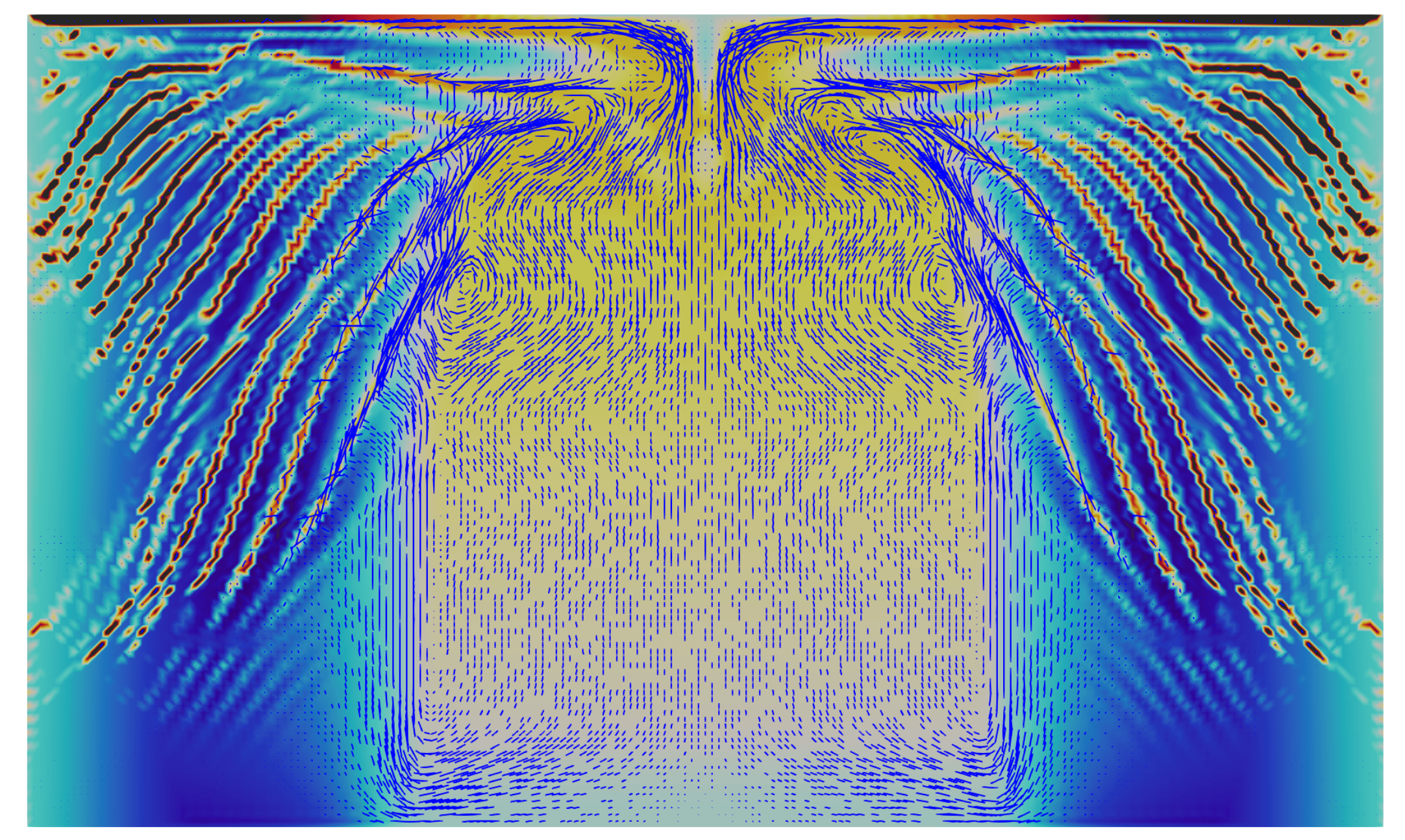
Figure: Simulation of macrosegregation of Pb-18wt% Sn binary alloys
Simulations and modelling of novel electronic devices and materials from an electronic device packaging perspective
\(\textbf{Yingjia Gao}^{1,2}, \textbf{Preslav Aleksandrov}^{2}, \textbf{Andrei G. Shvarts}^{1}, \textbf{Lukasz Kaczmarczyk}^{1}, \textbf{Chris Pearce}^{1}, \textbf{Asen Asenov}^{2}, \textbf{Vihar P. Georgiev}^{1,2}\)
\(^1 \textit{Glasgow Computational Engineering Centre, James Watt School of Engineering, University of Glasgow}\) \(^2 \textit{Device Modelling Group, James Watt School of Engineering, University of Glasgow}\)
In the rapidly advancing landscape of electronic device packaging, the simulation and modelling of heterogeneous materials are essential in ensuring optimal performance and reliability
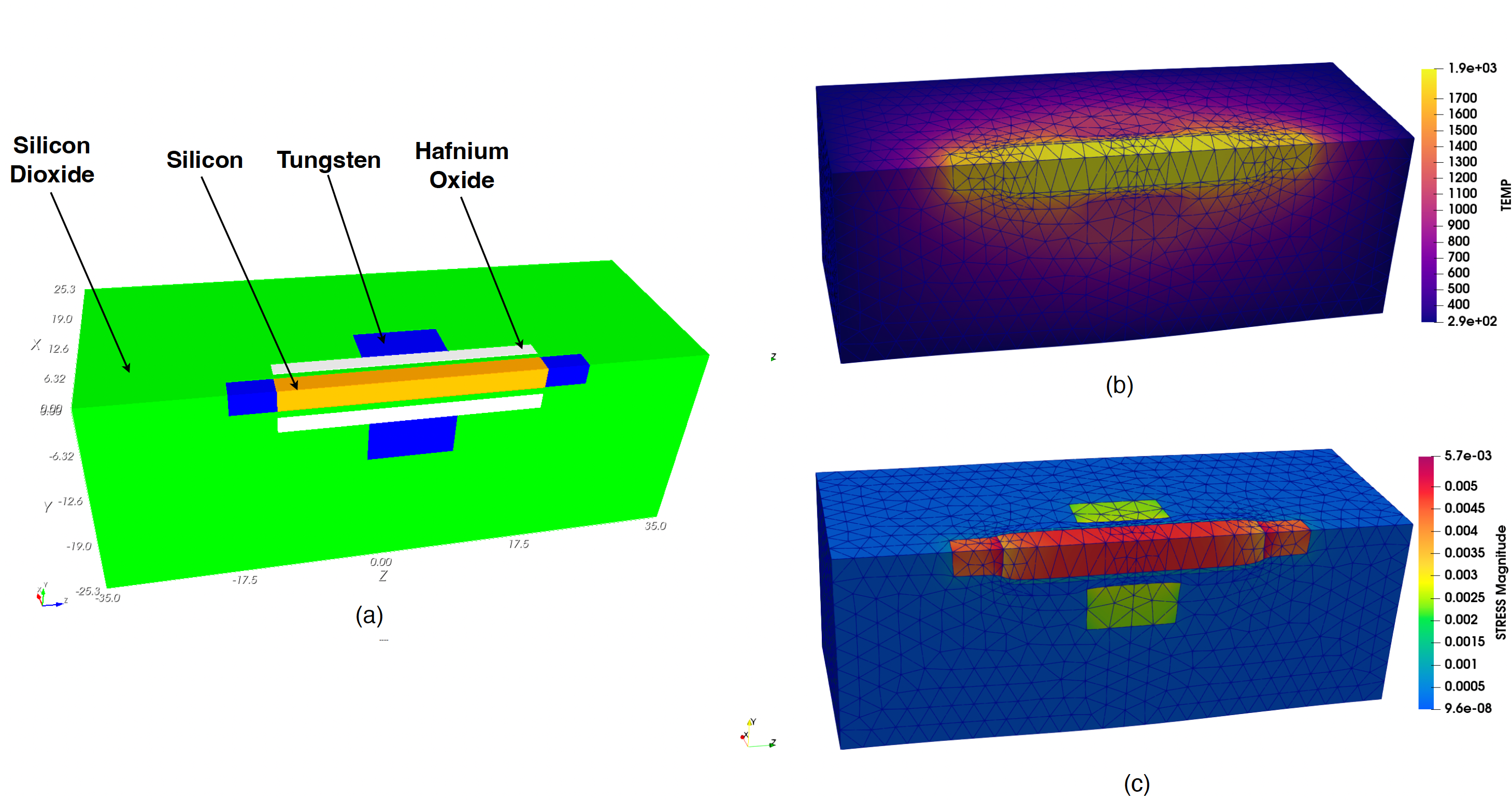
[46]. The aim of this project is to develop advanced computational framework for simulation of electronic devices, including packaging of such devices. This multifaceted exploration includes mechanical analysis, thermal considerations about the complexities of heat transfer in chips, and electrical simulations of the intricacies of electron transport. Coupling these sub-problems forms a holistic approach, offering valuable insights into the chip packaging problem.
Due to the smaller nanoelectronic devices, the arrangement of the various components in the chip becomes more important
[31]. For example, the heat emitted by various components on the chip can lead to crack forming and propagation in the material used for packaging. As a result such effects could lead to decreasing of the performance not only on specific chip but also on the whole system. The best way to capture the compexity of the problem is by utilizing the finite element method simulations wich can give a precise physical and material analysis of all the mechanical, thermal and electrical effects inside the electronic device and chips
Figure: (a) A sketch of the nanowire transistor surrounded by insulating packaging material. (b) Temperature distribution in the system. (c) Stress in the nanowire transistor due to heating
Evaluating the forces involved in bubble management in DMEK surgery – a mathematical and computational model with clinical implications
\(\textbf{David Lockington}^{2}, \textbf{Gordon MD Brown}^{2}, \textbf{Chris Pearce}^{1}, \textbf{Lukasz Kaczmarczyk}^{1}\)
\(^1 \textit{Glasgow Computational Engineering Centre, James Watt School of Engineering, University of Glasgow}\) \(^2 \textit{Tennent Institute of Ophthalmology, Gartnavel General Hospital, 1053 Great Western Road, Glasgow, G12 0YN, United Kingdom}\)
The model
[47] assumed incompressibility for both fluids within realistically achievable pressure ranges. Cahn-Hilliard Navier-Stokes equations were discretised through the application of the Finite Element Method. Mathematical modelling and computer simulation showed bubble size, corneal curvature and force intensity influences surface tension support for DMEK tissue in Scenario in the following figure. Scenario B demonstrated complex, uneven distribution of surface pressure on the DMEK graft during uncontrolled bubble release. Uneven pressure concentration can cause local tissue warping, with air/fluid displacement via capillary waves generated on the fluid-air interface adversely impacting DMEK support. We have quantitatively and qualitatively modelled the forces involved in DMEK adherence in normal circumstances. We have shown releasing air/gas can abruptly reduce DMEK tissue support via generation of large pressure gradients at the liquid/bubble/graft interfaces, creating negative local forces. Surgeons should consider these principles to reduce DMEK graft dislocation rates via optimised bubble size to graft size, longer acting bubble support and avoiding rapid decompression.
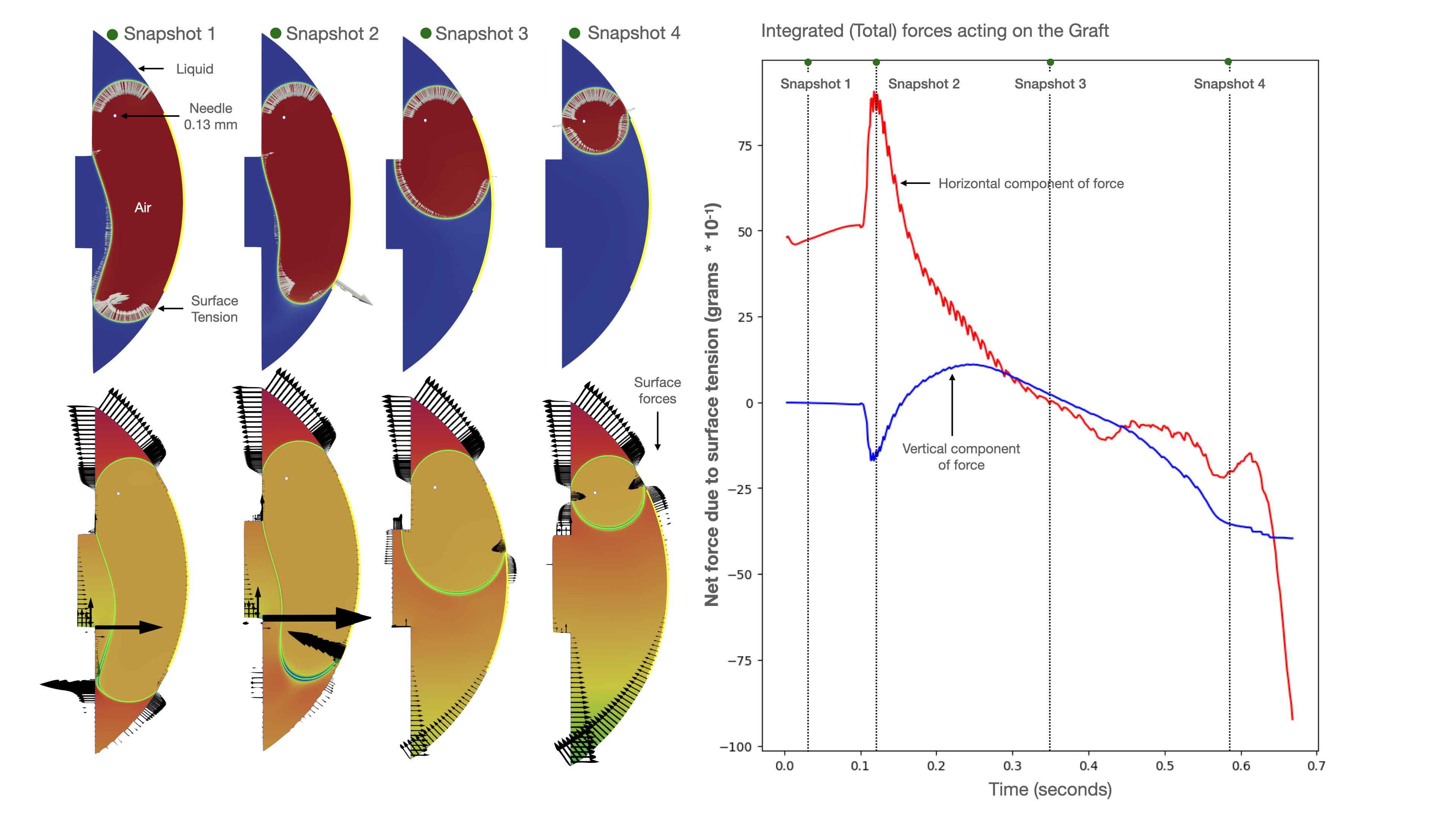
Figure: DMEK graft and four snapshots in time of air bubble release in the vertical position, with a corresponding graph showing total horizontal and vertical forces acting on the DMEK graft. Subsequent snapshots represent the transition from the complete bubble-filled stage (Snapshot 1) to the final mobile bubble stage (Snapshot 4). The top-left illustration shows the bubble in red and the fluid/liquid in blue. The bottom-left illustration shows the distribution of pressure as the bubble is released
A finite element model updating approach for the characterisation of piezoelectric materials
\(\textbf{Ignatios Athanasiadis}^{1*}, \textbf{Andrei Shvarts}^{1}, \textbf{Sakineh Fotouhi}^{2}, \textbf{Lukasz Kaczmarczyk}^{1}, \textbf{Sandy Cohran}^{2}, \textbf{Chris Pearce}^{1}\)
\(^1 \textit{Glasgow Computational Engineering Centre, James Watt School of Engineering, University of Glasgow}\) \(^2 \textit{Centre for Medical and Industrial Ultrasonics, James Watt School of Engineering, University of Glasgow}\)
The physical response of piezoelectric materials is governed by the strong coupling of mechanical and electrical phenomena as their mechanical deformation generates electric potential gradients and vice versa. There has been an increasing interest in these materials due to the breadth of engineering applications where they have been successfully used, such as power harvesting and smart sensing
[19],
[52]. Therefore, the accurate determination of piezoelectric materials' parameters is essential which has lead to an increasing demand for improved numerical tools to support this scope. In this work, we propose a coupled numerical framework for piezoelectric material characterisation. For our analysis, experimentally obtained electric impedance phase diagrams are used, where a cubic specimen is subjected to a voltage pulse that generates its mechanical and voltage damping oscillation in the figure. Thereafter, the experimentally obtained resonance frequencies and their amplitude are used to determine a set of objective functions that are minimised via the Finite Element Model Updating method (FEMU) in order to find the material parameters. The minimisation procedure involves a series of fully implicit dynamic FEM analyses with changing the material input parameters between simulations. The proposed framework is aimed to aid new piezoelectric material technologies where more complex structures are involved and to be extended to account for more physical phenomena.
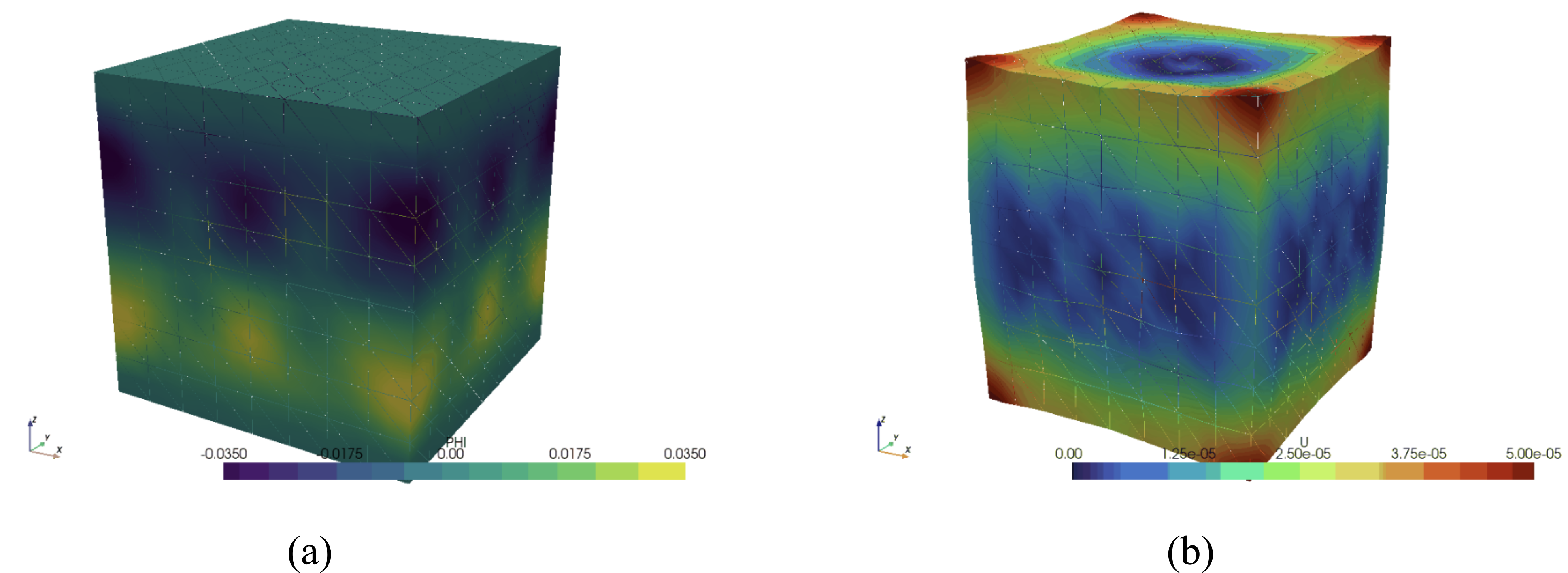
Figure: A snapshot of simulation results - (a) electric potential, (b) mechanical displacement
Numerical Simulation of Triboelectric Nanogenerators
\(\textbf{MD Tanzib Ehsan Sanglap}^{1}, \textbf{Lukasz Kaczmarczyk}^{1}, \textbf{Andrei G. Shvarts}^{1}\)
\(^1 \textit{Glasgow Computational Engineering Centre, James Watt School of Engineering, University of Glasgow}\)
Triboelectric nanogenerator (TENG) is a cutting-edge energy harvester that transforms mechanical excitation to electric energy during contact electrification and electrostatic induction. Prior research which studied the electrostatic characteristics of TENG performance mostly relied on approximate analytical models. However, an accurate numerical model is crucial for understanding the relation between the output performance and various geometric and material parameters of the device. This study aims to develop a detailed finite element model to predict the TENG behaviour at different configurations. The investigation underlines the generation of the open circuit voltage, \(V_{oc}\) due to the surface charges at the interface between dissimilar tribo-layers of the contact-separation model of TENG. A series of simulations were conducted to anticipate \(V_{oc}\) at different air gaps between the layers. The results in figure shows the comparison between FEM results and approximate analytical solutions. The numerical solution conforms to analytical for the small gaps, while for the larger gaps, it converges with the approximations. We anticipate gaining a deeper understanding of the performance characteristics through the FE model and corresponding quantitative analysis. Furthermore, we aim to develop a multi-physical FE framework encompassing contact mechanics, electrostatics and electric circuit equations, to facilitate the optimization and design of TENGs.
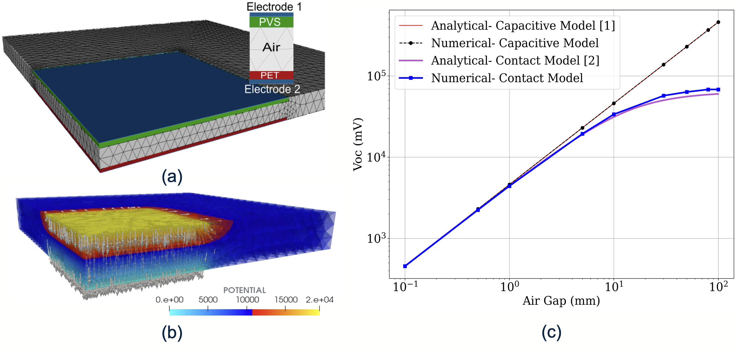
Figure: (a) Implementation schematics. (b) FEM results for the potential and electric field between two tribo-layers. (c) Comparison of approximate analytical models and MoFEM simulations to investigate the dependence of the open-circuit voltage on the air gap