 |
v0.14.0 |
|
v0.14.0 |
This series of basic lessons is intended to give new developers an introduction to the implementation of bespoke finite element codes in MoFEM library. It is assumed that you, as a new MoFEM developer, have at least an essential fluency in C++ programming and that you are an engineer/physicist/mathematician who has an interest in solving Partial Differential Equations (PDEs) using finite element methods. In these lessons, the mathematical abstractions are kept as basic as possible.
If you follow one of the lessons and fail to understand its content, it is most likely our fault not expressing ideas clear enough. If that is the case, you can ask questions on our Q&A, or join us our group discussion platform on Slack. Your comments are valuable to us and help to improve the work. If you are keen to contribute, starting from improving tutorials is the best way.
All problems presented in this tutorial, except the first one, are in 2D. However, the implementation is designed in such a way that one can extend them to 3D with relative ease. Once you have a good understanding of the tutorial, as an exercise, you can implement the 3D extension.
This is the beginning of a series of tutorials which are intended to be expanded, in a consistent way, into a much larger project in which a broad class of nonlinear problems can be solved.
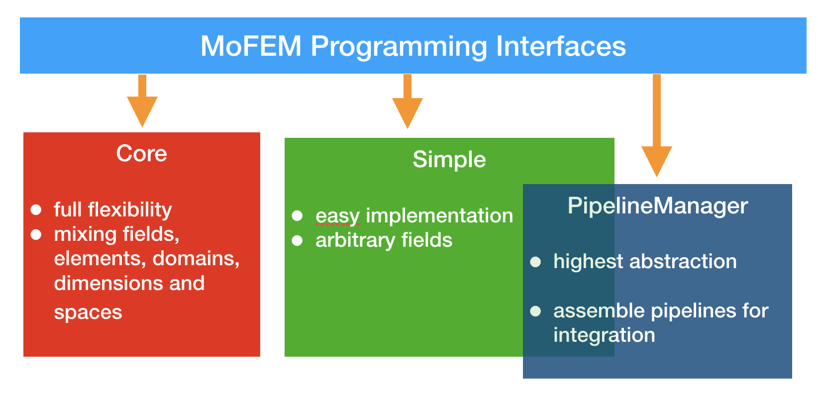
MoFEM provides different interfaces with varying purposes and level of abstractions.
Categorised by purposes, there are two main groups of the interfaces. The first the group involves the bookkeeping which builds the rules (definition) for managing fields, finite elements, problems, which enable to construct DOFs, and define the structure of matrix and vectors, for serial and parallel problems. This group includes Core interface and Simple interface. Meanwhile, the second group deals with the operator implementation that calculates the actual value of each component in matrices/vectors that is going to be filled using one of the interfaces in the previous group. An example of an interface that belongs to this second group is PipelineManager interface.
Categorised by the level of abstraction, there are also two main groups of interfaces, namely higher-level and lower-level. The higher-level abstraction, e.g. Simple interface enables faster and simpler implementation but with limited flexibility in terms of a range range of problems that can be solved. Meanwhile, the lower-level abstraction, e.g. Core interface, offers the highest flexibility but can be harder to use and demands more detailed knowledge about the design MoFEM and how it works.
For the purpose of preliminary tutorials, we use the combination of Simple and PipelineManager interfaces that complement each other. More details about the two interfaces are explained in the following parts.
The Simple interface is used to add approximation fields (e.g., density, displacement, etc.). It also delivers a Discrete Manager (DM), which is a class that handles the management of DOFs between the mesh and the discrete system. Instances of DM can create global matrices and vectors. The Simple interface allows for multiple fields, integration on the domain, boundary and skeleton. It also permits heterogeneous mesh, e.g. meshes with triangles and quads, and heterogeneous approximation order. However, it assumes that fields and finite element spaces, such as \(L^2\), \(H^1\), etc., are set on the entire domain or boundary of the mesh. This is not always the case, as a problem may consist of various fields at different parts of the domain. The Simple interface also assumes that the problem being implemented has fixed dimension, and does not allow for mixing of dimensions, such as shells (2D in 3D ambient space), beams (1D in 3D ambient space) and solid elements. Despite the above-mentioned restrictions, Simple interface enables fast implementation of a large class of problems.
MoFEM philosophy of finite element implementation relies on operator pipelines. Pipelining is a concept used to organise operations in a sequential manner that run to assemble the right-hand-side vector or stiffness matrix. The PipelineManager interface is used to simplify the creation of operator pipelines. The User data operator (UDO), is an abstract class that can be specialised to implement various kinds of operators. For example, a differential operator that calculates the gradient of a field, calculate strains, or use previously calculated strain in the pipeline to calculate stress, and finally, calculate the right-hand-side vector. In other words, the pipeline is a method to break a complex problem into simple tasks or data operators.
It might not be apparent from the outset why we need Simple interface and PipelineManager interface. It will later become clear that PipelineManager interface expands the capabilities of the Simple interface. Simple interface provides a clear way of handling DOFs, i.e. approximation fields on the mesh, managing entities and problems on which finite elements are set. However, it does not provide a mechanism to assemble a vector of internal forces and tangent matrix or integrate a finite element. Such tools are provided by PipelineManager interface and will be dealt with in later tutorials in the series.
About MoFEM data structures, you can learn from MoFEM Architecture. However, we recommend looking that document later. We recommend going to lesson one, i.e. lesson1.