 |
v0.14.0 |
 |
v0.14.0 |
Traditional finite element codes are element-centric (type of element defines approximation space and base) and therefore cannot exploit the potential of emerging approximation methods. MoFEM software utilises recent advances in finite element technology and modern data structures, enabling the efficient solution of difficult, multi-domain, multi-scale and multi-physics problems. In this code, the design of data structures for approximation of field variables are independent of the specific finite element (e.g. Lagrangian, Nedelec, Rivart-Thomas) being used, such that finite element is constructed by a set of lower dimension entities on which the approximation fields are defined.
Therefore, different approximation spaces (H1, H-curl, H-div, L2) can be arbitrarily mixed in finite elements to create a new capability for solving complex problems efficiently. Approximation space defines adjacency of DOFs on entities, the number of DOFs on an entity is independent on approximation base (at least for polynomials). The base on the entity is a trace of the base on the element, and opposite relation works, base on the entity is propagated to the element.
MoFEM data structures allow easily to enrich approximation fields or modify base functions, e.g. to resolve singularity at crack front. Applying this technology, it is effortless to construct transition elements between domain with different problem formulation and physics (e.g. from two-field mix-formulation to single-field formulation), or elements with anisotropic approximation order (e.g. in solid-shells with arbitrary high-order on the shell surface and arbitrary low-order through-thickness).
This approach also sets the benchmark in terms of how finite element codes are implemented, introducing a concept of user-defined data operators acting on fields that are associated with entities (vertices, edges, faces and volumes) rather on the finite element directly. Such an approach simplifies code writing, testing and validation, making the code resilient to bugs.
MoFEM has not developed and will not develop all capabilities from scratch. Instead, it integrates advanced scientific computing tools for Algebra (PETSc and associated tools), Topology (MOAB and associated tools) and data structures from Boost. The resilience of this ecosystem is ensured by solid fundation of its components and by a dynamic and established group of developers backed by a constantly growing user base. MoFEM focuses its attention on complexities related to finite element technology and uses abstractions like field entity, DOF (degree of freedom), finite element and problem.
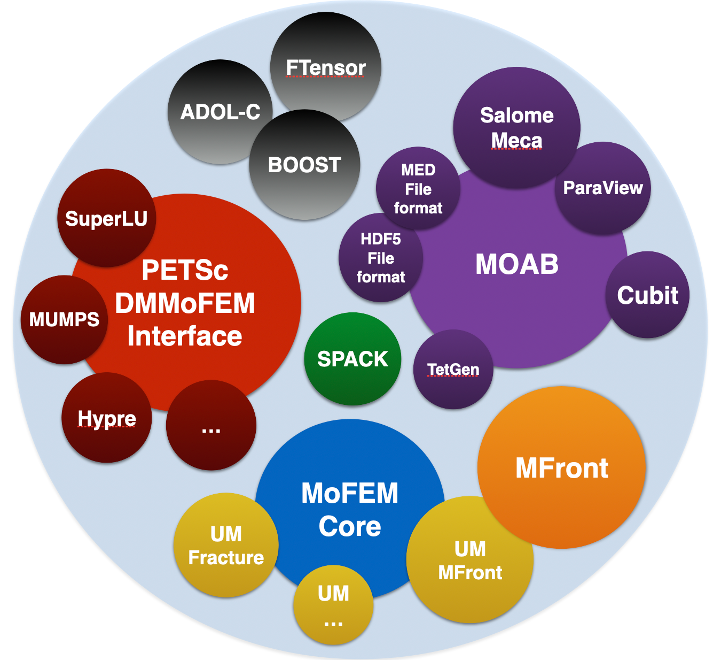
Finite element software is a complex ecosystem managing mesh and topology related complexities, sparse algebra and complications related to approximation, integration or dense tensor algebra at the integration point level. Each element by itself is a standalone complicated problem. MoFEM ecosystem is composed of three parts, MoAB managing complexities related to topology, PETSc managing complexities related to sparse algebra with solvers and finally MoFEM core library managing complexities directly related to the finite element method. Each part has its design objectives and appropriate programming tools from a spectrum of solutions can be selected [41]. MoFEM makes PETSc an integral part of the code by extending PETSc via DMMOFEM interface (several other functions work directly on PETSc objects). MoAB on the other hand is adopted for internal data storage. PETSc is designed to be fast, whereas MoAB aims to be memory efficient.
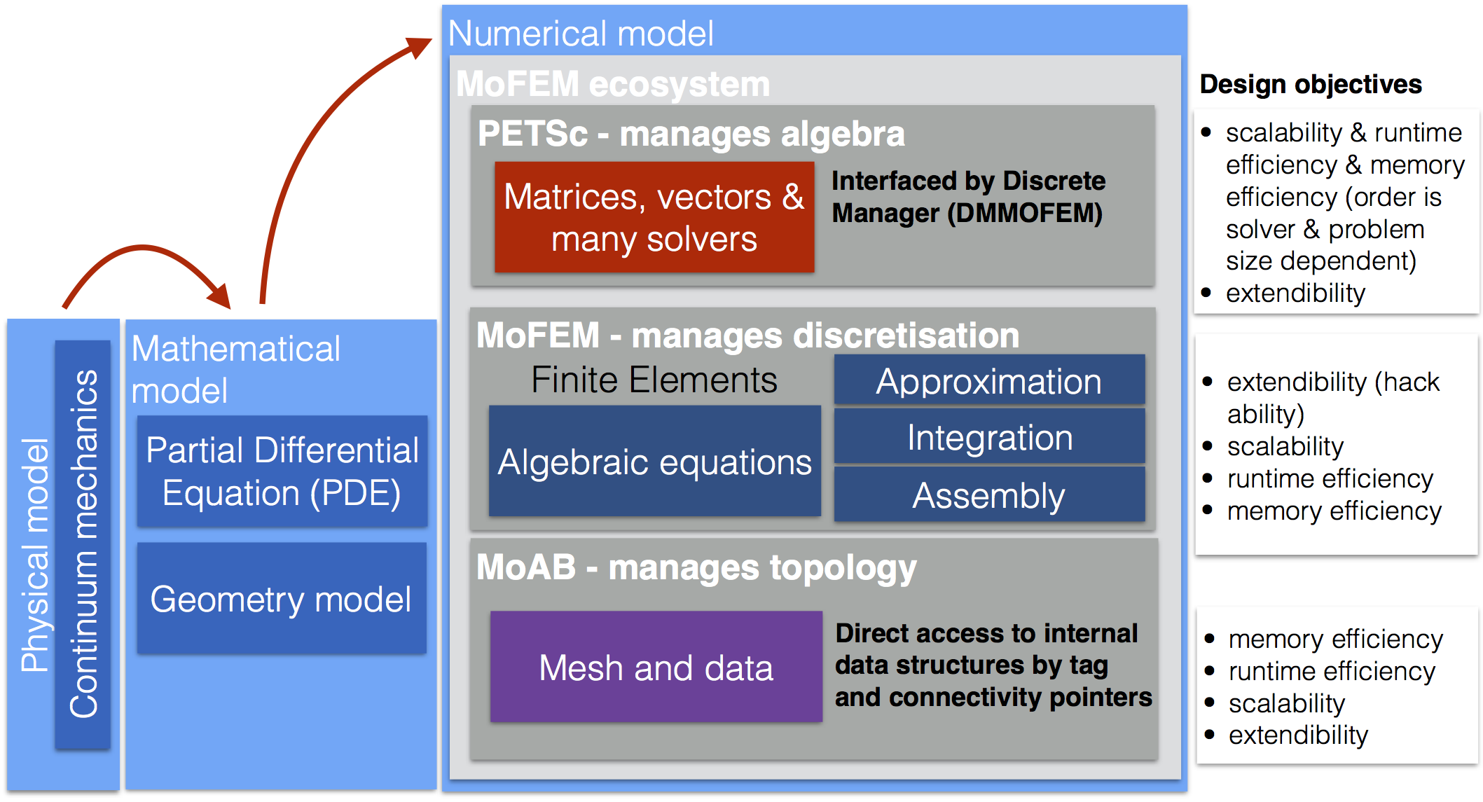
Code development, with no difference from engineering, is a compromise of different goals. The first primary design objective of MoFEM is to develop flexible and extendable code that is easy to test and bug search. Very often, we spend more time implementing finite elements than the time needed to run the analysis itself. Flexibility and extensibility allow for rapid development of finite elements for non-standard and complex problems. Utilising PETSc and MoAB scalability is the second important design objective. Nowadays, we can have easy access to the computing clusters through cloud computing or local/regional supercomputers. Third, the core library cannot compromise runtime efficiency and use of computer memory with care.
The finite element entity is composed of subentities, like nodes, edges, faces (triangle, quad, etc.) and volumes (tetrahedron, hex, prism, etc). The element is implemented by evaluating base functions, indices, data on each entity in the domain of the element. The developer does not directly implement finite elements for a given predefined type, but UserDataOperators operate on the finite element entities. In such a method, the order of approximation and the shape of the finite element does not influence how the user implements a problem.
Moreover, unlike in common finite element codes, the choice of field space and base space is independent of the type of element, it happens before we select the domain of integration and finite elements on it. Concepts like the periodic table of finite elements, or zoo of finite elements are obsolete.
We use the concept of a finite element as a domain on which integration rule is constructed and base functions are evaluated. The finite element has an auxiliary set of data, for example, a measure of the domain, i.e. volume, area or length. Some elements carry information about normal, direction depending on the dimension of the finite element domain. The base finite element interface can be seen here MoFEM::ForcesAndSourcesCore. Note that most of the derived classes do not alter finite element core behaviour, add only type-specific functionality, f.e. appropriate rule of integration for given shape and dimension of element entity. Except for special cases, differential operators could be implemented unrespectfully on the type of finite element entity. The structure and finite element interaction with user data operators are shown in the figure below
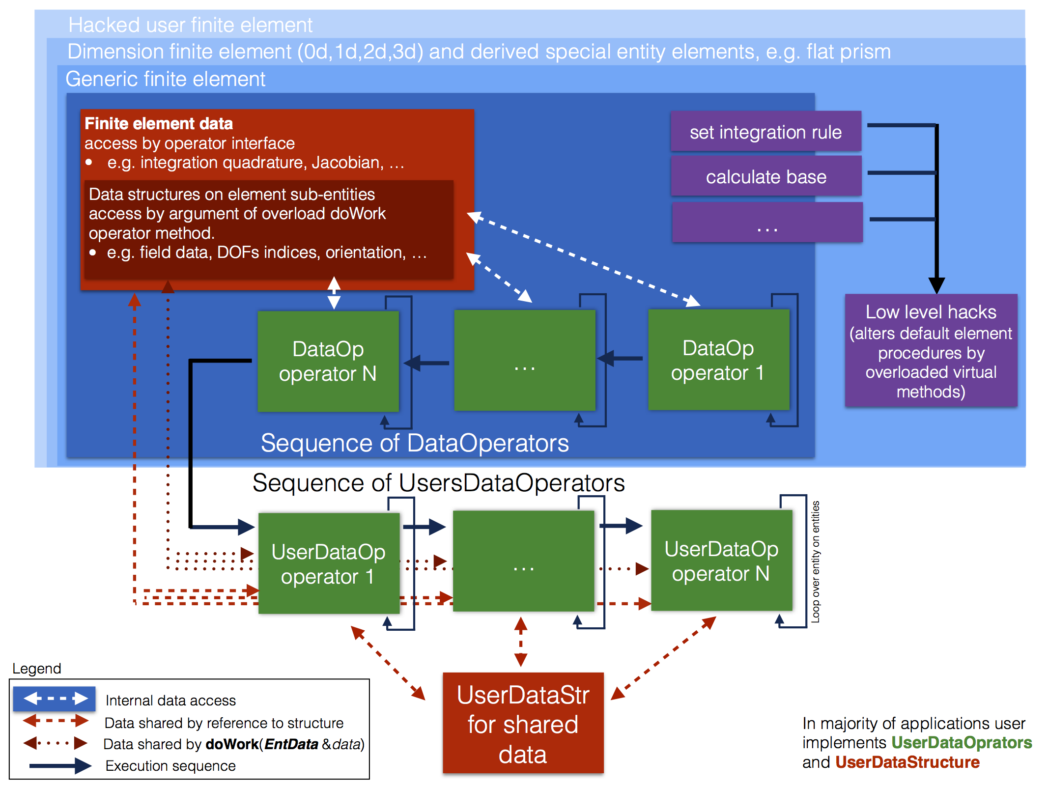
The fundamental role in finite element implementation plays MoFEM::ForcesAndSourcesCore::UserDataOperator. The generality of this technology range of applications 0d-2d or 3d, with Nitsche's method or with H-div or H-curl spaces. The UserDataOperator are operated in three typical ways, first (OPROW/OPCOL) are usually used to evaluate the right-hand side vectors, second (OPROWCOL) to evaluate the left-hand side matrices, and third, often use to modify base functions of given space. First two are intrinsically linked to operations on particular fields, the last one is abstract and should not be used to assemble vectors and matrices. Type of operator is set by overloading function doWork. Operators are run in sequence as they are added to finite element and executed for each entity on that element. If for a given field number of DOFs or base functions on an assigned entity is zero, such entity is not evaluated.
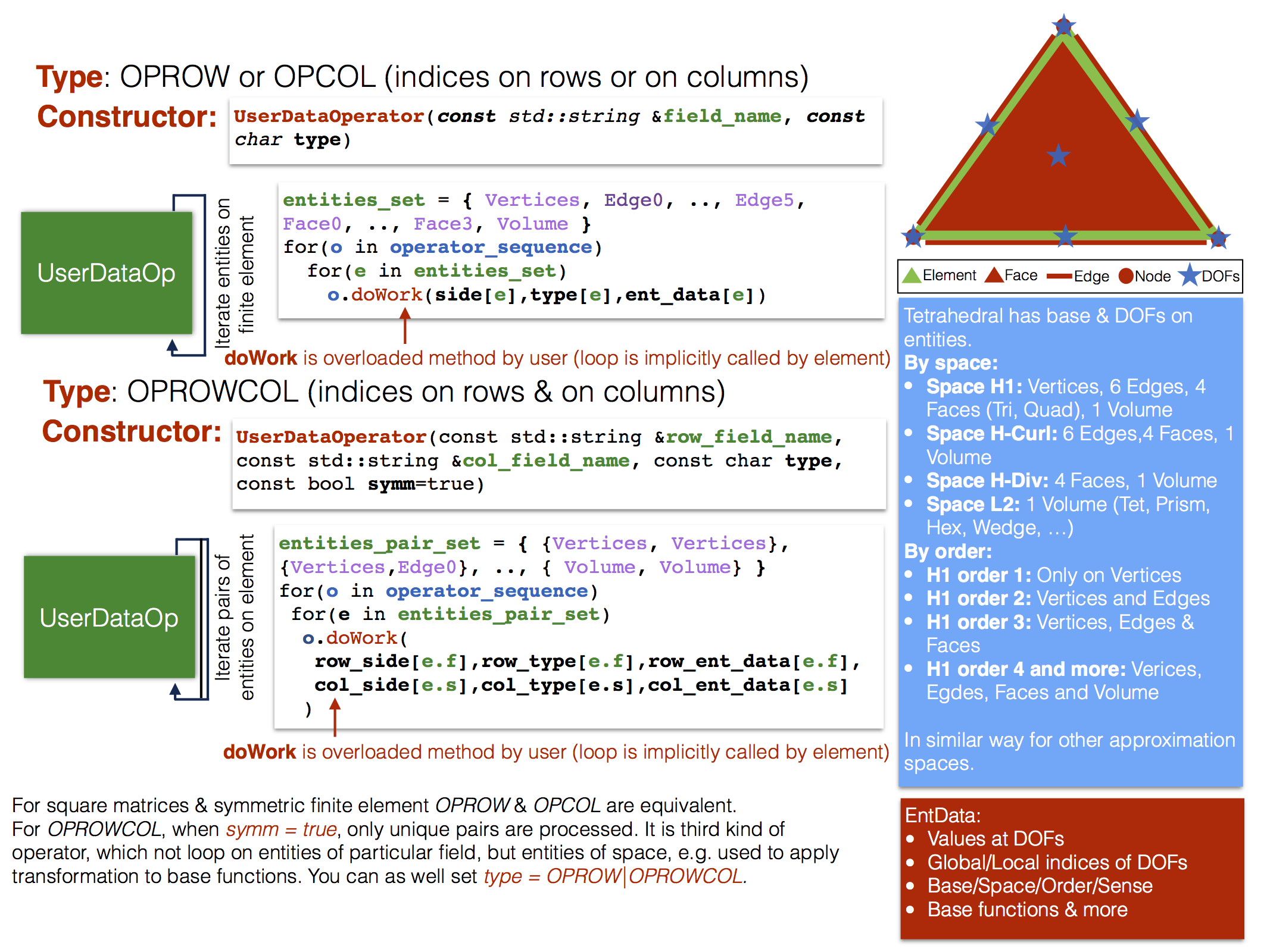
Note that the data and the algorithm operating on that data are localised and grouped by both elements and entities. Elements and entities share data structures avoiding unnecessary memory allocation and de-allocation. However, the motivation for this development is code elasticity (resilience to change and openness for new finite element technologies) and reusability. With relatively small code changes, large group of problems can be implemented and last but not least this approach enables modularisation and testing of each element independently.
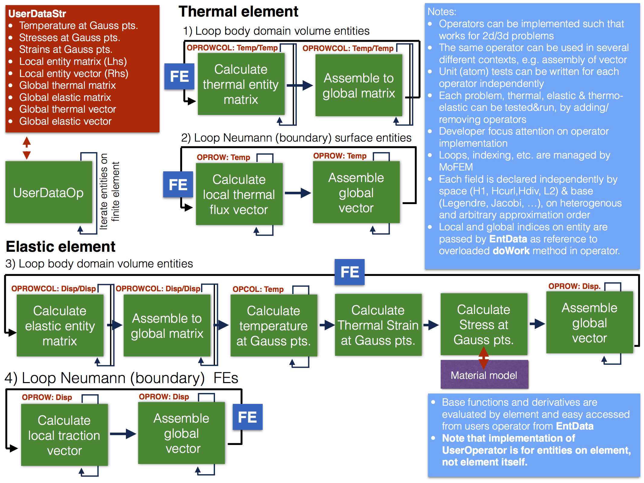
Above example reflects how an engineer would formulate the problem for linear thermoelasticity, calculate physical quantities like strain, stress, temperature or flux and assemble a system of linear equations to solve it staggered method. Another way approaching this problem to think regarding differential operators. One can implement set of operators,
\[ (\nabla u ,\nabla u),\;(\nabla \cdot \tau, u),\;(u,u) \]
and example, assembly of
\[ \mathbf{A} = (\nabla u,\nabla u)_\Omega = \int_\Omega \nabla \mathbf{u} \cdot \nabla \mathbf{v} \textrm{d}\Omega \]
take form
Typically, internal data structures are hidden from the user and there is no need to access them directly. In the core library, no single problem or finite element in the classical sense is implemented. Core library only provides functionality for finite element implementation and application code development. For that reason, repositories of the core library and user modules are in separate independent locations.
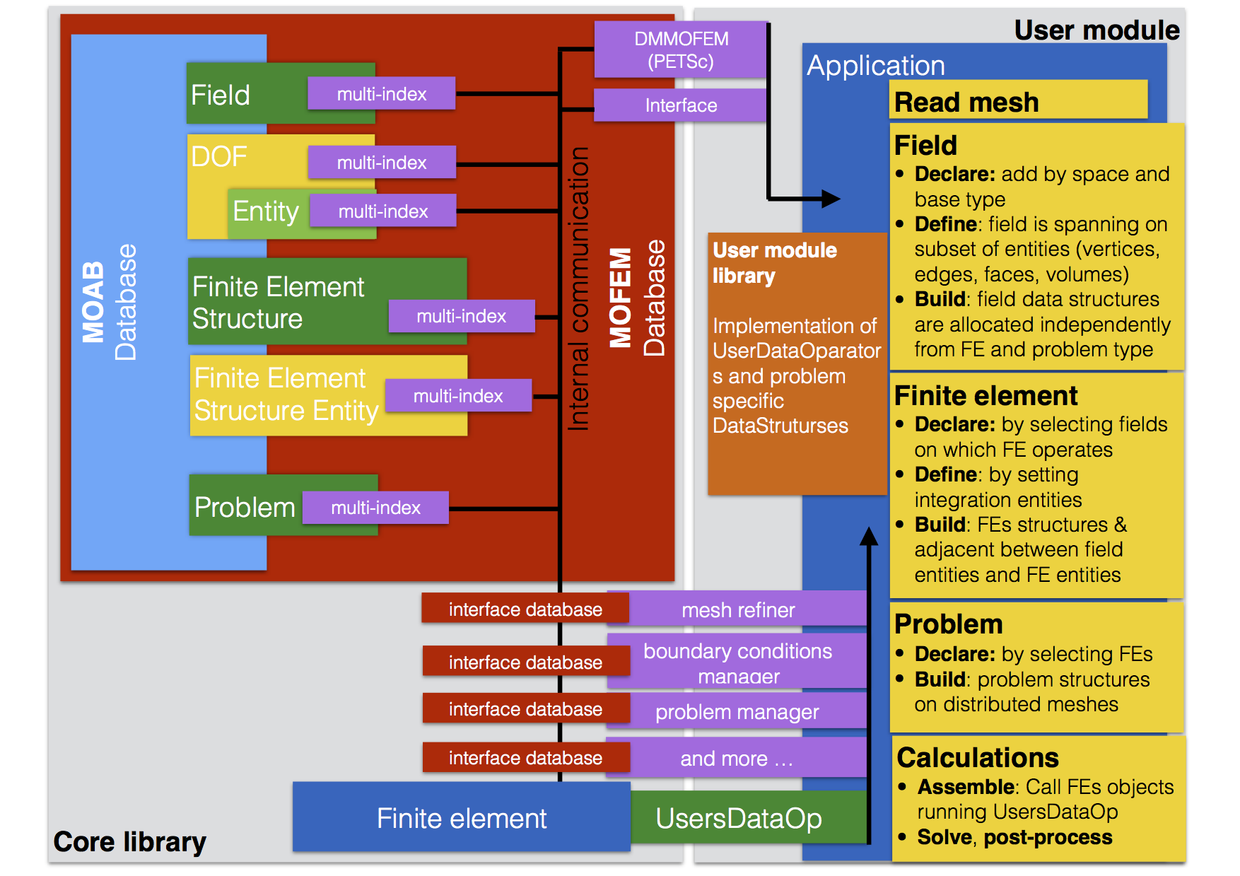
In the figure above on first instant, a developer is interested in the implementation of user data operators and tasks in the yellow boxes. It has to define fields, which span on some entities and set approximation order. For example
Similarly, defining finite element set implement integration domain and build internal data structures. Note, finite element structure is separated from implementation. The same element can have several implementations, which work on some set of user data operators. Moreover, the same problem defined on the same field and data structures, can be implemented in separate modules. Also, several user modules exchange data by common MoFEM database, without knowing how other modules have been implemented, that enables simplified cooperation between developers.
You don't have to know how internal data structures work, like the driver of a car, does not necessarily knows how a spark plug works. So if you get bored, you can skip this part.
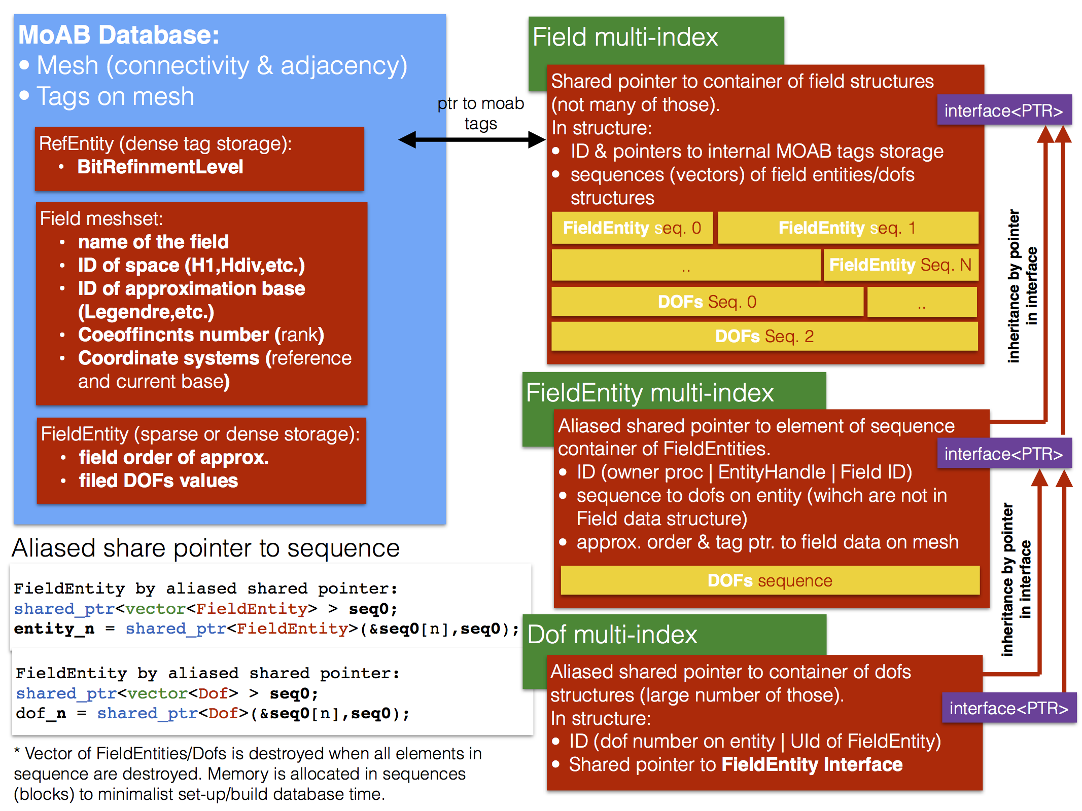
However, sometimes it is useful to know details when something goes wrong. The objective is to have an extendable and flexible data structure, which can manage a wide range of approximations. At the same time, it should be easy and fast access to data structures, have short set-up time and exhibit memory efficiency without redundancies. This aim is realised by use boost multi-indices, aliased shared pointers and vector sequences. See for example MoFEM::NumeredDofEntity or MoFEM::DofEntity. Data are accessed by multi-indices, for example, defined in DofsMultiIndices.hpp, FieldEntsMultiIndices.hpp or FieldMultiIndices.hpp. Similar data structures are created for finite elements and problems.
