 |
v0.14.0 |
|
v0.14.0 |
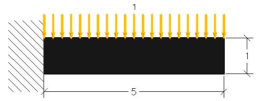
In this tutorial, the use of Salome is explained as a pre-processor for MoFEM analysis. The version of the Salome used for this tutorial is a part of Salome-Meca 4.0.6 programme. A step-by-step procedure is given here to solve a linear-elastic cantilever beam problem subjected to uniform pressure shown below.
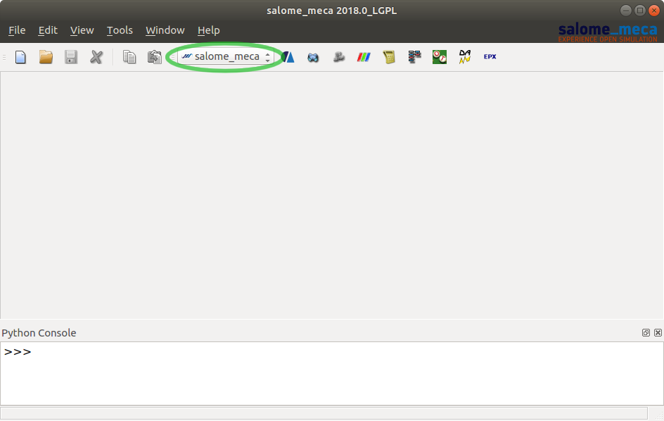
First of all, after openeing change the working environment to "Geometry". This can be done by navigating the drop-down menu shown in a green circle in Figure 2. This will prompt opening of an existing project or creationg a new one.
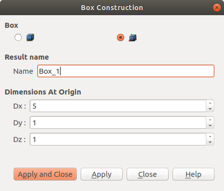
To create a simpe beam with a square cross section, a box function is sufficient. Navigation using tabs is as follows:
New Entity -> Primitives -> Box
After applying the changes, the box should now appear in the viewer. To create selectable surfaces, explode the box as follows:
New Entity -> Explode (choose Face option and apply)
To ease the creation of mesh groups later, rename the body faces with recognisable names. Parts can be selected by clicking on them in the viewer (if they are set visible in the object browser). This highlights the selected object in the object browser and there it can be renamed via right click of the mouse.
Once the required modelling is present in the geometry section, change the workspace to Mesh with the same dropdown menu shown in Figure 2. The viewer is empty as there is no mesh yet created but the box should still be in the in the Object Browser. Select the box and mesh it by:
Mesh -> Create Mesh
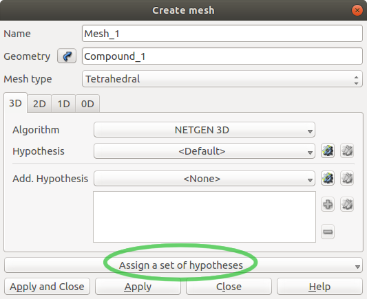
The way and how fine the object is meshed is chosen in the hypotheses highlited in Figure 4. In this example 3D tetraheadral mesh is chosen with 0.3 as the maximum length of an edge of any element. With the settings set, compute the mesh by:
Mesh -> Compute
The mesh should now be visible in the viewer.
The mesh groups can be created based on parts which are already present in the geometry section.
Mesh -> Create Group
In the group type select "Group on geometry". An example group setting is shown in Figure 5 bellow.
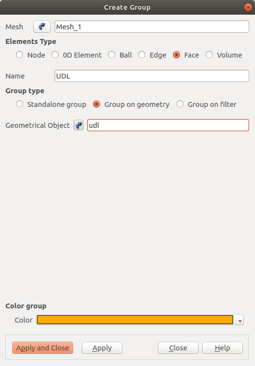
The required groups are: applied pressure (face), fixed support (face) and the box itself (volume).
With all of the groups defined, export the mesh to .med file which can be read by MoFEM.
File -> Export -> MED file
Once the mesh (.med file) with required groups is created, material properties, loading and boundary conditions are assigned via cantilever_elasticity.cfg file. Also config file set the material propeties to the blocks. Material properties used in this case are:
In cantilever_elasticity.cfg file, change the numbers assigned to blocks, i.e. [block_4] for volume, to correspond to the correct groups. The config file is as follows
To confirm that the properties are assigned to correct groups, read the mesh with the following command (replace sal_beam_mesh.med with the name of your mesh file)
Now the cantilever_elasticity.cfg file can be applied to the mesh by
A new file called out.h5m is created in the current folder. It is advised to rename this file to, for example, input_mesh.h5m. Subsequently, the following command is used to run the elastic analysis on the beam problem:
This will create out.h5m file, which is then converted to out.vtk file using
The out.vtk file can be viewed in Paraview. For the cantilever beam problem, the output is shown in the following figure.