v0.14.0
Benchmarks crack propagation tests (EDF Tests)
Note
Tests in this document have been made in the older version of the code. Command lines and input mesh files have to be updated to reproduce results below. Work is in progress on updating documentation.

The following tests have been designed to check the capability and robustness of crack propagation tools in MoFEM.

Three test are investigated,

  • test case 1: loading of a brick slice
  • test case 2: loading on a full-size brick
  • test case 3: loading on a full-size with partial length keyways

Full test specification and geometrical description is available here: link.

This work is motivated by the inability of commercial finite element codes to simulate crack propagation in brittle materials in structural elements with complex geometries.

How to cite us?

DOI

Solution scheme and theoretical context

All calculations presented in this document are based on the theoretical developments presented in paper by Kaczmarczyk & Pearce [38], whereby the equations for equilibrium and propagation of the crack front are derived from first principles, i.e. the first law of thermodynamics and principle of maximum dissipation of energy (particular case of second low of thermodynamics). The methodology is formulated in the context of configurational (Eshelby) mechanics. Conservation of momentum is solved in both the spatial and material domains. The spatial (or physical) domain can be considered as a description of what we physically observe and the material domain is the evolving reference domain due to crack evolution. The crack front is subjected to a constraint emerging from the Griffith fracture criterion.

In addition to the theoretical developments, to realise the propagating crack with finite elements, a method based on face splitting is proposed in [38]. However, in the current work, an alternative and novel approach is proposed, leading to an implicit, smooth and consistent crack propagation. In the following tests, cracks are propagated by directly displacing crack front nodes in the material reference configuration. This approach is distinct to well known methods, where the crack propagation is realized by enriching nodes (X-FEM), re-meshing or face splitting. This method enables the crack front to move continuously by an arbitrary, implicitly calculated, distance, based on crack front equilibrium condition subjected to Griffith criterion; in classical approaches, the crack is extended by some discrete predefined distances.

In the presented approach, smooth evolution of the crack geometry results in a certain amount of mesh distortion. To resolve this, an efficient mesh smoothing technique is implemented in VolumeLengthQuality (see [38]) and surface constraints are implemented in SurfaceSlidingConstrains. This result in a variant of the Total Arbitrary Lagrangian Eulerian Formulation (T-ALE), such that mesh smoothing does not influence the crack propagation.

In addition to mesh smoothing, a face flipping, node merger and edge splitting algorithm is incorporated to fully propagate the crack over the entire thickness of the body. After each converged load step, topological mesh changes are introduced to improve mesh quality in the neighborhood of the crack front. It should be noted that at this point, the crack geometry is fixed and not influenced by mesh changes. In other words, re-meshing and/or face flipping is not used here to realise the crack propagation but to maintain mesh quality. Poor mesh quality is a major source of error.

A finite element in T-ALE setting is implemented in NonLinear Elastic Element. Spatial and material forces are calculated, which drives body deformation in the physical space and crack front displacements in the material space. Material forces acting on the crack front are equilibrated by Griffith forces (material resistance forces). Griffith force element is implemented in GriffithForceElement.

In this approach crack propagates only in mode-I. The crack front position and direction are calculated implicitly at the same time, in such a way that maintains equilibrium at the crack front at the end of load step. In classical approaches, equilibrium is condition is not used, only the Griffith (or other) criterion is applied, and crack is extended based on the stress state at the beginning of the load step. Since crack evolution is strongly nonlinear, this classical approach can result in a mixed mode crack extension, demanding an appropriate calculation of crack direction for mixed mode, leading to an explicit calculation of the crack path. It is important to stress that propagating cracks in mode-II or mode-III are usually not observed experimentally in homogeneous isotropic solids. A crack subjected to mode-II or mixed mode loading, curves or kinks and propagates in a direction that maintains locally pure mode-I conditions at the tip [22] [34]. This is consistent with the approach we have adopted, achieving maximum dissipation of energy in the generation of new crack area and crack front equilibrium.

Quasi-static crack propagation

In all tests, it is assumed that the crack is propagating quasi-statically. This assumption is satisfied by controlling the force such that material displacements of the crack front lead to slow total crack area increase. To achieve this, a specific version of the arc-length technique is adopted, see [38] for details. Since crack propagation is understood here as an evolution of the body topology and a strongly non-linear process, each increment of the crack area is controlled during the incremental iterative process, and the crack area size is automatically adapted to obtain the desired number of Newton-Raphson iterations for each load step.

Algorithm

  • solve system of nonlinear algebraic equations for displacements, crack front position and load factor. Note that the crack front position is not directly controlled and a load factor is implicitly calculated to increase total crack area by the desired quantity.
  • post-process results and record at given step
  • adapt next crack area increment to get desired number of iterations (4-5 iterations) for next step
  • update mesh for next step (merge nodes, split edges, flip faces such that mesh quality in crack front neighborhood is improved)

Tests

Brick slice with slot (Loading with pure bending applied to slot edges)

Statistics

  • 33565 degrees of freedom (this is number at the start of the analysis, but does not change significantly during analysis)
  • 133 load Steps
  • 67 seconds - approximate step time (Laptop, 2.3 GHz Intel Core i7, 4 cores)

Results

Brick slice (animation)

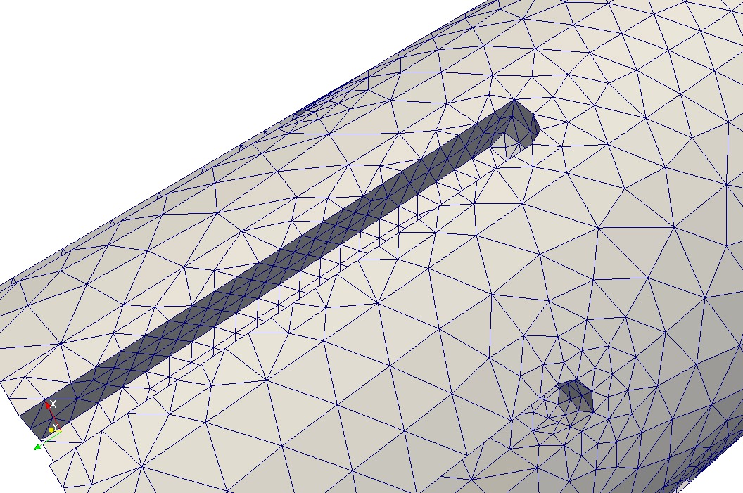
A brick slice is subjected to forces applied on top and bottom slot edges. Edge forces have the same magnitude but opposite directions, that produce a couple and pure bending moment is applied, see link for details.

Crack is initialised at the keyway corner. The size of the initial notch is defined by the mesh size. Initial analyses show that size or shape of initial notch does not influence significantly the final crack propagation.

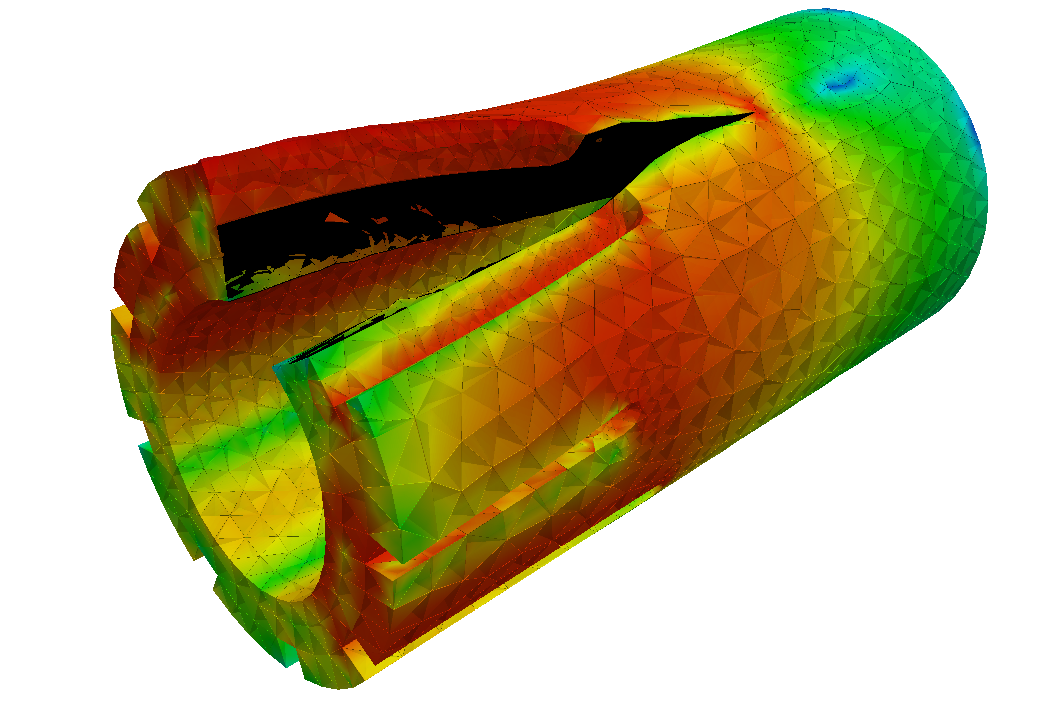
Since the slice is subjected to pure bending, at any arbitrary cross section of the brick, no net axial force is present. As a result, material points in the vicinity of the crack front are subjected to tension; near the bore, material is in compression. Therefore, the crack is prevented from propagated fully through the brick and an elastic hinge is created at the end of the analysis.

It can be noted that any partial crack propagation through the bore would lead to self penetration of the crack surfaces, since compressive stresses are acting next to the bore, to transfer the externally applied bending moment. It is postulated that inability of the presented method to propagate the crack through to the bore validates the crack front equilibrium equations derived in [38]. The crack can only propagate if the crack tip is subjected to tension. Given that only pure bending is applied, the crack front can only move as far as the neutral axis (in extreme). The neutral axis is half the distance between crack front and bore surface, where tension and compression is applied, respectively. Therefore, in each load step, in the limit, a crack can propagate half of its previous distance, and so on for the following steps. As a result, the crack will only reach the bore in an infinite number of steps (this justification is valid for ideal structure, assuming of small strains and displacements).

Brick slice (crack snapshots)
Brick slice (crack snapshots - side view)
Deformed brick slice (crack snapshots - side view)

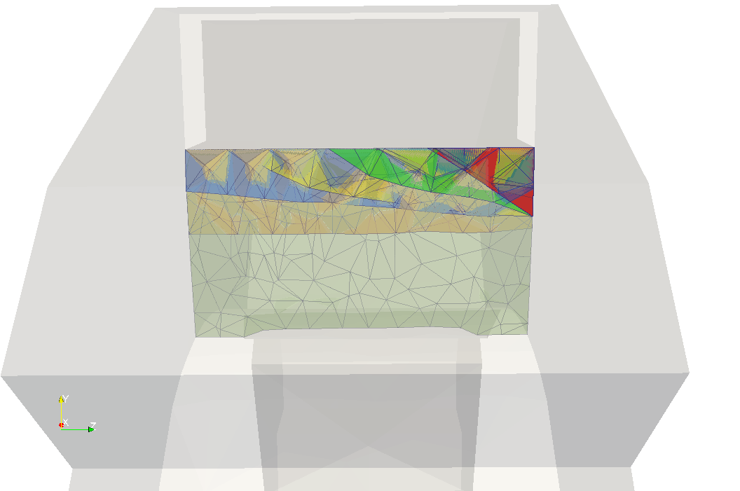
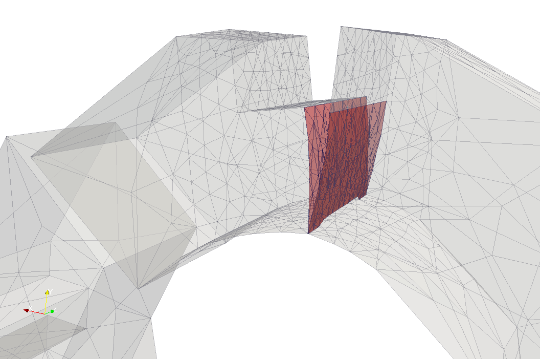
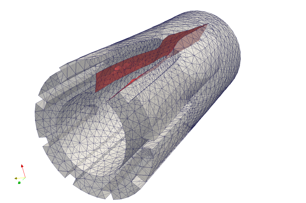
The figures above show snapshots of crack propagation, where the red triangle represent initial crack notch. Note that crack propagation is not planar and bends slightly towards the slot.

Load-displacement path (Brick slice)

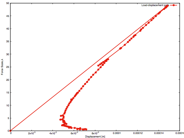
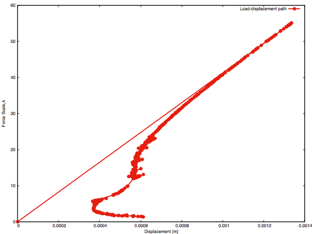
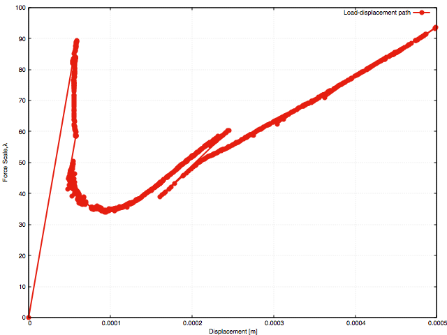
The figure above shows the load-displacement path, with generalised displacement on the x-axis and force load factor, on the y-axis. The generalised displacement does not represent a particular point on the structure, but its value is work conjugate to the applied forces and is calculated from the following formula,

\[ \Psi = \frac{1}{2} u (\lambda f),\; \textrm{thus}\quad u = 2 \frac{\Psi}{\lambda f} \]

where \(f=1\)[N] is reference force, \(\Psi\) is elastic energy, \(\lambda\) is load factor and \(u\) is generalised displacement. The generalised displacement is used to present results objectively. The load-displacement plot is obtained using arc-length control, such that the external force is adapted to maintain the crack area during each load each step. This results in a unique maximum dissipative load path. Since maximum dissipation of energy drives crack propagation direction, this plot represents the equilibrium path. The crack surface is the result of maximum release of energy, therfore any other shape of the crack front or crack surface would release less strain energy. However, for further verification those calculations should be repeated for denser meshes and higher order of approximation order, to verify the quality of the finite element approximation itself.

Crack area vs Elastic Energy (Brick slice)

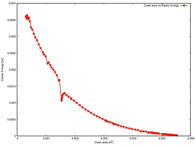
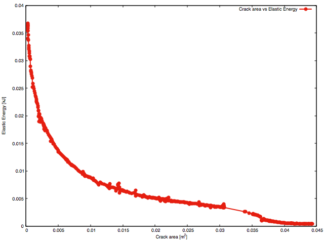
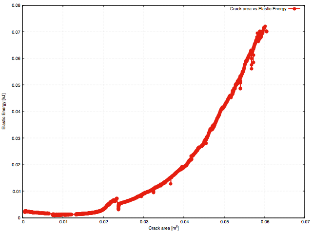
It should be noted that the energy release rate is assumed constant ( \(g_c\)) and a material parameter. However on the structural level, the crack area vs strain energy plot shows that the slope of curve is not constant over the analysis. The explanation for varying slope of curve is explained by two factors;

  • The length of the crack front where energy is released is not constant. It grows up to the point where the crack reaches the opposite side of the specimen. After that getting shorter, ultimately to reach a fixed length, equal to brick width - see snapshots of crack surface.
  • Topology of the body is evolving and the displacement vector, at points where external force is applied, is changing. Thus, the work of external forces is varying from one step to another.

Note, that it can be easily shown (both analytically and numerically), that for a long (infinite) plate with a notch, the slope on the crack area vs strain energy plot is constant, since crack front length is constant and forces are applied remotely from the fracture process.

One can also note a jump in the response on both of the plots above. This is the outcome of a numerical artifact. In the current algorithm, by default, once a crack front approaches a corner, the crack is automatically extended to pass the corner. Increasing mesh density will reduce this effect. In practice, this algorithm feature can be switched off to avoid this behaviour. Cracking of the corner does not signifciantly influence the results.

Input data and running the code

reset
create vertex 0.10085 0.084623 0
create vertex 0.17273 0.144938 0
create vertex 0.225483 0.044851 0
create vertex 0.225483 0.016475 0
create vertex 0.187763 0.016475 0
create vertex 0.187763 -0.016475 0
create vertex 0.225483 -0.016475 0
create vertex 0.225483 -0.044851 0
create vertex 0.191155 -0.127726 0
create vertex 0.16660 -0.152281 0
create vertex 0.139928 -0.125609 0
create vertex 0.125609 -0.139928 0
create vertex 0.152281 -0.16660
create curve vertex 1 vertex 2
create curve vertex 2 vertex 3
create curve vertex 3 vertex 4
create curve vertex 4 vertex 5
create curve vertex 5 vertex 6
create curve vertex 6 vertex 7
create curve vertex 7 vertex 8
create curve vertex 8 vertex 9
create curve vertex 9 vertex 10
create curve vertex 10 vertex 11
create curve vertex 11 vertex 12
create curve vertex 12 vertex 13
Curve 8 copy rotate -45 about z repeat 1
create curve vertex 13 vertex 25
Curve 3 4 5 6 7 8 9 10 11 12 14 copy rotate -90 about z repeat 3
create curve vertex 50 vertex 51
create curve vertex 72 vertex 73
delete curve 46 45 44 43 42
Curve 1 copy rotate 10 about z
create curve vertex 82 vertex 100
create vertex -0.13165 0 0
create curve vertex 99 vertex 1 vertex 103 circular
merge vertex all with vertex all
create curve vertex 66 vertex 68
create surface curve 1 2 3 4 5 6 7 8 9 10 11 12 14 13 15 16 17 18 19 20 21 22 23 24 25 48 26 27 28 29 30 31 32 33 34 35 36 49 37 38 39 40 41 51 50 52
sweep surface 1 direction z 1 distance 0.1
delete curve 47 53
delete vertex 103
webcut volume 1 with plane vertex 151 vertex 82 vertex 122
webcut volume 1 with plane vertex 146 vertex 73 vertex 127
imprint volume all
merge volume all
unite volume 2 4
unite volume 2 1
brick x 0.018 y 0.02 z 0.03
webcut volume 6 with plane vertex 181 vertex 178 vertex 185
delete volume 7
move Vertex 180 location vertex 148 include_merged
chop volume 5 with volume 6
imprint volume all
merge volume all
Sideset 100 curve all
Sideset 100 curve 159 181 164 170 151 205 207 208 199 198 206 204 209 218 169 150 171 149 158 161 184 remove
Nodeset 101 vertex 153 152 100 99 108 1 2 109
Sideset 102 surface all
Sideset 102 surface 57 73 59 50 93 82 81 83 63 remove
Sideset 10200 surface 59 73 57
Sideset 10201 surface 93
Sideset 200 surface 83
Sideset 201 curve 199
create Displacement on surface 2 dof all fix 0
create force on curve 142 force value 1 direction -0.766 0.643 0
create force on curve 144 force value 1 direction 0.766 -0.643 0
block 1 volume all
block 1 name 'MAT_ELASTIC'
block 1 attribute count 2
block 1 attribute index 1 9.6
block 1 attribute index 2 0.2
volume all scheme Tetmesh
volume 3 2 size auto factor 8
volume 9 8 size auto factor 5
mesh volume all

The following program calculates the Griffith forces for initial crack configuration, allowing user to define refinement level at the crack front. It generates a starting file out_spatial_2_0.h5m for the crack propagation program.

convergence_study.sh -f brick_slice_b2.cub -l 1 -g 1.4e-7 -o 2 -r 0 -d BrickSlice -p 4

where:

  • -f brick_slice_b2.cub mesh file
  • -l 1, initial load factor
  • -g 1.4-7, material parameter, strain energy release rate (Note that unit is [J/m^2 10^(-9)])
  • -o 2, set approximation order to quadratic functions
  • -r 0, set mesh refinement level at crack front, 0 no refinementt
  • -d BrickSlice, directory where results are stored

This program does the crack propagation,

arc_length.sh \
-f BrickSlice/out_spatial_2_0.h5m -a 1e-6 -g 1.4e-7 \
-n 2000 -i 6 -t 5e-10 \
--my_arc_alpha=1e-4 \
--my_other_side_constrain=1 \
-d BrickSlice \
-p 4

where additional parameters are,

  • -a initial crack area increment, over the analysis, the step size is adapted to achieve the desired number of iterations. It controls the arc-legth method.
  • -i 6, desired number of iterations for load step.
  • -t 5e-10, tolerance for Newton-Raphson method
  • -my_arc_alpha 1e-4, it scales residual for arc-length method, i.e. what is tolerance for residual of controlling function with respect to residual of global system of equations.
  • –my_other_side_constrain=1, indicate that initially some nodes of crack front are at corner edge, defined by intersection body (skin) surface.

Full size brick with slot (Loading with pure bending applied to slot edge)

Statistics

  • 119588 degrees of freedom (this is number at the start of the analysis, but does not change significantly during analysis)
  • 550 load steps
  • 67 seconds - approximate step time (ARCHIE-WEST, 24 cores)

Results

Full brick (animation)

The crack propagation for full brick is similar to previous example. Crack is initiated form corner triangular notch on one of the brick sides, propagates to opposite side and then towards the bore. Since pure bending moment is applied and no axial force is present, elastic hinge is created and brick is not exhibiting a full break.

Full brick (crack snapshots 1)
Full brick (crack snapshots 2)
Full brick (crack snapshots 3)
Full brick (deformed shape)

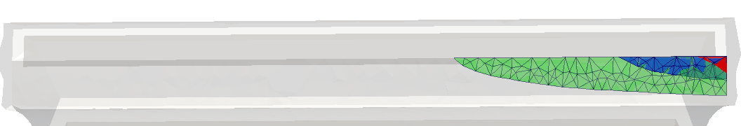
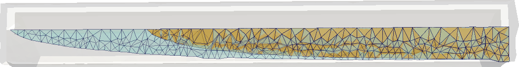
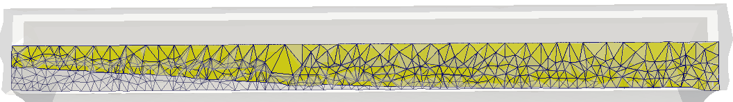
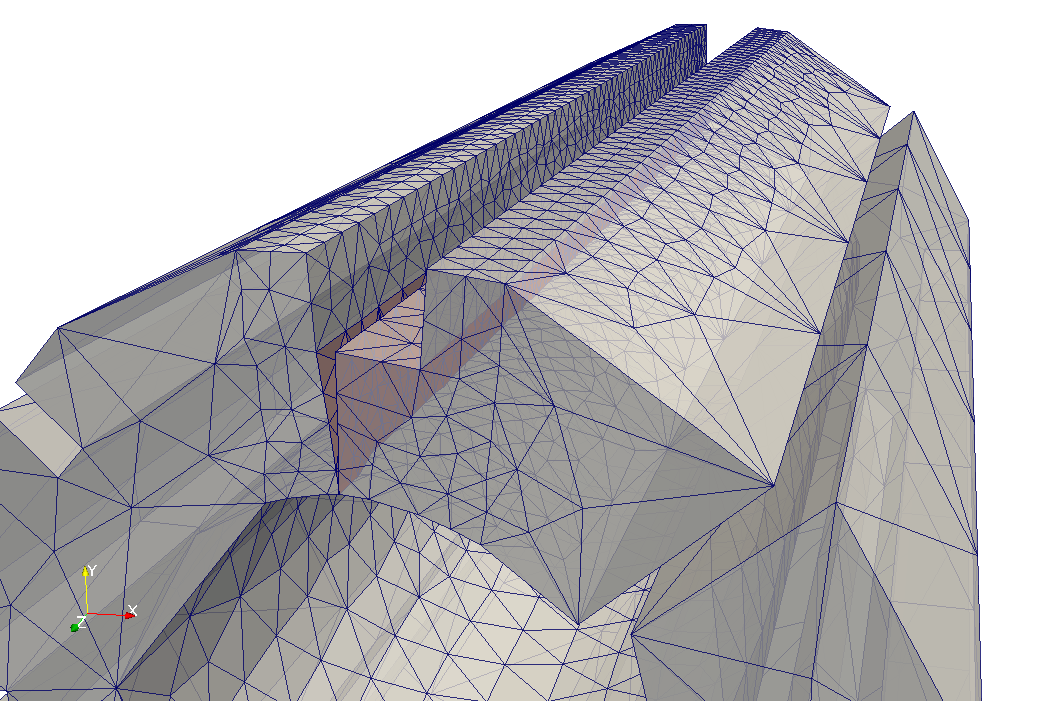
In the figures above, it is shown how crack propagates in subsequent snapshots. The crack is predominately planar during the analysis, however it approaches the surface of the bore at an angle - this can be observed in the figure presenting the brick deformation.

Load-displacement path (Full brick)
Crack area vs Elastic Energy (Full brick)

In the above, plots of load-displacement response and strain energy against crack area are shown. These are more complex than for the brick slice. Three stages of crack propagation can be identified; propagation of the crack to the opposite brick surface, propagation to the bore and finally creation of elastic hinge (where the equilibrium path achieves a quasi plateau).

Analysis of load path enables better understanding of component safety, noting that if

  • \(\delta u_i > 0\) and \(\delta \lambda_i > 0\) crack propagation is stable,
  • \(\delta u_i > 0\) and \(\delta \lambda_i < 0\) crack propagation is stable if kinematic loading is applied, conditionally stable if static loading is applied,
  • \(\delta u_i < 0\) and \(\delta \lambda_i < 0\) crack is unstable, unless both displacements and loads are controlled,

where \(\delta u_i\) and \(\delta \lambda_i\) are increments of displacements and forces at load step \(i\).

It can be noted that for brick slice and full brick, crack propagation is unstable, until snap-back point at the end of analysis where elastic hinge is created.

Input data and running the code

The full brick model is very similar to brick slice. The only difference is brick length which is set according to the specification in link. Code was run with the same input parameters as in previous example, only difference is that number of processors was increased to 24 and calculations were executed on ARCHIE-WEST.

reset
create vertex 0.10085 0.084623 0
create vertex 0.17273 0.144938 0
create vertex 0.225483 0.044851 0
create vertex 0.225483 0.016475 0
create vertex 0.187763 0.016475 0
create vertex 0.187763 -0.016475 0
create vertex 0.225483 -0.016475 0
create vertex 0.225483 -0.044851 0
create vertex 0.191155 -0.127726 0
create vertex 0.16660 -0.152281 0
create vertex 0.139928 -0.125609 0
create vertex 0.125609 -0.139928 0
create vertex 0.152281 -0.16660
create curve vertex 1 vertex 2
create curve vertex 2 vertex 3
create curve vertex 3 vertex 4
create curve vertex 4 vertex 5
create curve vertex 5 vertex 6
create curve vertex 6 vertex 7
create curve vertex 7 vertex 8
create curve vertex 8 vertex 9
create curve vertex 9 vertex 10
create curve vertex 10 vertex 11
create curve vertex 11 vertex 12
create curve vertex 12 vertex 13
Curve 8 copy rotate -45 about z repeat 1
create curve vertex 13 vertex 25
Curve 3 4 5 6 7 8 9 10 11 12 14 copy rotate -90 about z repeat 3
create curve vertex 50 vertex 51
create curve vertex 72 vertex 73
delete curve 46 45 44 43 42
Curve 1 copy rotate 10 about z
create curve vertex 82 vertex 100
create vertex -0.13165 0 0
create curve vertex 99 vertex 1 vertex 103 circular
merge vertex all with vertex all
create curve vertex 66 vertex 68
create surface curve 1 2 3 4 5 6 7 8 9 10 11 12 14 13 15 16 17 18 19 20 21 22 23 24 25 48 26 27 28 29 30 31 32 33 34 35 36 49 37 38 39 40 41 51 50 52
sweep surface 1 direction z 1 distance 0.825
delete curve 47 53
delete vertex 103
webcut volume 1 with plane vertex 151 vertex 82 vertex 122
webcut volume 1 with plane vertex 146 vertex 73 vertex 127
imprint volume all
merge volume all
unite volume 2 4
unite volume 2 1
brick x 0.018 y 0.02 z 0.03
webcut volume 6 with plane vertex 181 vertex 178 vertex 185
delete volume 7
move Vertex 180 location vertex 148 include_merged
chop volume 5 with volume 6
imprint volume all
merge volume all
Sideset 100 curve all
Sideset 100 curve 159 181 164 170 151 205 207 208 199 198 206 204 209 218 169 150 171 149 158 161 184 remove
Nodeset 101 vertex 153 152 100 99 108 1 2 109
Sideset 102 surface all
Sideset 102 surface 57 73 59 50 82 81 83 63 87 91 remove
Sideset 10200 surface 59 73 57
Sideset 10201 surface 87 91
Sideset 200 surface 83
Sideset 201 curve 199
create Displacement on surface 2 dof all fix 0
create force on curve 142 force value 1 direction -0.766 0.643 0
create force on curve 144 force value 1 direction 0.766 -0.643 0
block 1 volume all
block 1 name 'MAT_ELASTIC'
block 1 attribute count 2
block 1 attribute index 1 9.6
block 1 attribute index 2 0.2
volume all scheme Tetmesh
volume 3 2 size auto factor 8
volume 9 8 size auto factor 4
mesh volume all

Loading full brick with partial length keyways

Statistics

  • 117209, Degrees of Freedom (this is number of nodes at being of analysis, but does not change significantly during the analysis)
  • 1639 load steps
  • 67 seconds - approximate step time (ARCHIE-WEST, 24 cores)

Results

Long brick (animation)

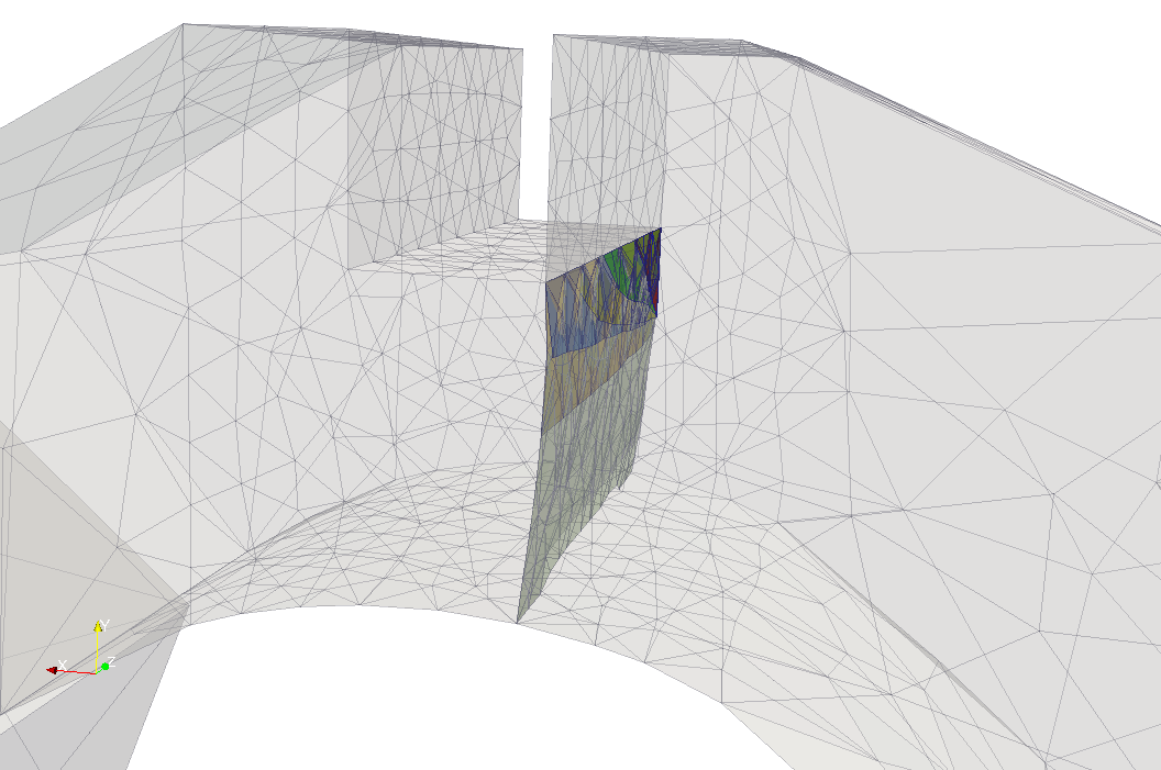
This test has complex geometry and crack propagation path compared to test 1 and test 2. See details about loading and geometry here link. A tearing load is applied at key way edges, mimicking loading from interstitial key. In this example, the crack initially propagates along the edge and then to the bore. Next it propagates along the brick to its opposite side across the brick cross section.

Long brick (crack surface)
Long brick (crack surface - side view)
Long brick (deformation)

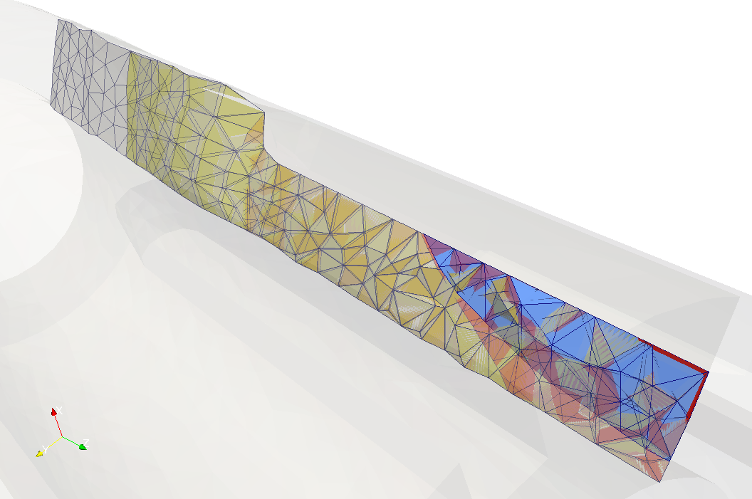
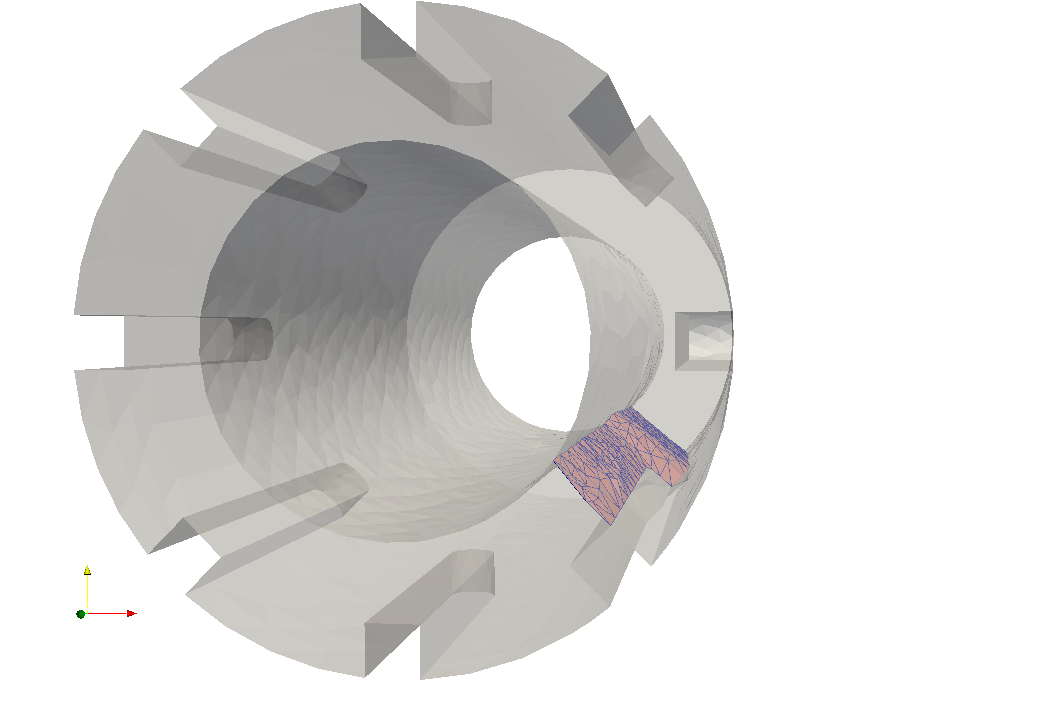
In the figures above, it can be seen that crack propagation has several stages, and initially is slightly curved and it approaches the bore at an angle. Once the crack front passes the end of the keyway, there is a distinctive curve for some distance.

In the simulation of this test, the code encountered some difficulties due to the relatively coarse mesh. Calculations have been stopped just before crack front reach opposite side due to deterioration of mesh quality. This difficulty will be removed in next MoFEM release.

Load-displacement (Long brick)
Crack area vs Elastic Energy (Long Brick)

Studying the load-displacement path, it can be noted that it reflects the propagatin of the complex crack path, where initially the crack is unstable. Next on the graphs it can be seen snap-back point, before crack front reaches the end of the keyway. From this point, crack propagation is conditionally stable. At the point where the crack front passing through the end of the keyway, a clear jump is visible on the load-displacement path. It can be noted that before and after that point, the tangent operator is positive and further increase of crack area demands increase of the loading force, i.e. crack propagation is stable. As a result, snap-through is possible, which can be interpreted as the loaded brick will partially break, and crack propagation will freeze if constant ultimate load is applied (assuming that inertia effects are neglected).

The above analyses show the predictive capability of the MoFEM crack modelling technique, allowing for better understanding of crack propagation, delivering not only crack topology but also insight into stability of the crack propagation. This will enable better judgment about safety of component under considered loading.

Input data and running the code

This test was run with the same command as in previous examples. Input mesh model is generated from the journal file shown below.

reset
brick x 0.03815 y 0.03810 z 0.36891
create Cylinder height 0.03810 radius 0.019075
rotate Volume 2 angle 90 about X include_merged
move Volume 2 location surface 1 include_merged
unite volume 1 2
brick x 0.03815 y 0.03810 z 0.27896
create Cylinder height 0.03810 radius 0.019075
rotate Volume 4 angle 90 about X include_merged
move Volume 4 location surface 13 include_merged
unite volume 3 4
create Cylinder height 0.944921 radius 0.227455
create Cylinder height 0.944921 radius 0.135
subtract volume 6 from volume 5
align Volume 3 surface 24 with surface 25
move Curve 24 midpoint location curve 33 except x y include_merged
Volume 3 copy rotate 90 about z repeat 3
subtract volume 3 7 8 9 from volume 5
align Volume 1 surface 12 with surface 56
rotate Volume 5 angle 45 about Z include_merged
move Curve 8 midpoint location curve 87 except x y include_merged
Volume 1 copy rotate 90 about z repeat 3
subtract volume 1 10 11 12 from volume 5
#color Volume 5 pink
brick x 0.018 y 0.03 z 0.04
webcut volume 13 with plane vertex 150 vertex 151 vertex 147
delete volume 14
move Vertex 153 location vertex 138 include_merged
chop volume 5 with volume 13
imprint volume all
merge volume all
brick x 0.1 y 0.5 z 1.0
chop volume 16 with volume 17
imprint volume all
merge volume all
split body 18
split body 19
unite volume 20 19
unite volume 20 21
imprint volume all
merge volume all
brick x 0.019075 y 0.03810 z 0.38799
move Vertex 223 location vertex 138 include_merged
subtract volume 22 from volume 18
modify curve 342 blend radius 0.02
rotate Volume all angle 180 about X include_merged
rotate Volume all angle -135 about Z include_merged
imprint volume all
merge volume all
Nodeset 101 vertex 125 124 126
split curve 347 distance 0.36891
Sideset 100 curve all
Sideset 100 curve 240 252 350 341 remove
Sideset 100 curve 237 239 231 242 232 238 241 remove
Sideset 100 curve 351 355 remove
Sideset 100 curve 268 272 275 273 271 270 274 269 remove
Sideset 100 curve 299 280 322 279 remove
Sideset 102 surface all
Sideset 102 surface 112 114 133 132 remove
Sideset 102 surface 169 170 165 119 remove
Sideset 10200 surface 169 170 165 119
Sideset 102 surface 149 136 remove
Sideset 10201 surface 149 136
Sideset 102 surface 113 remove
Sideset 200 surface 113
Sideset 201 curve 231
create Displacement on surface 89 88 91 102 101 104 100 97 98 dof 1 dof 2 dof 3 fix 0
create force on curve 359 force value 1 direction 3.2 2.8 0
create force on curve 198 force value 1 direction -1.1 -1.4 0
block 1 volume all
block 1 name 'MAT_ELASTIC'
block 1 attribute count 2
block 1 attribute index 1 9.6
block 1 attribute index 2 0.2
#delete mesh volume all propagate
volume all scheme Tetmesh
volume 18 15 size auto factor 4
volume 20 sizing function type skeleton scale 15 time_accuracy_level 1
volume 20 sizing function type skeleton
mesh volume all
Geometry of keyway for long brick

The long brick model has a modified geometry at the end of loaded keyway, to enable smooth transfer from a crack propagating along an edge to a crack propagating on the free outer surface. This simplification of the geometry is not expected to change final crack path; however, in the future, alternative options could be considered, both by different model with denser mesh and a dedicated algorithm for resolving such geometrical singularities.

Efficiency & robustness

Overall MoFEM performed the tests very successfully. The results showed sensitivity to the applied boundary conditions, showing differences between tests, in particular when the type of loading is changed. This demonstrates the predictive capability. MoFEM is able to deliver information about the crack surface, crack front propagation and load-displacements path, that enables engineers greater interpretation and safety and risk assessment.

Some of key future developments in the context of presented results are listed below;

  • The mesh is smoothed in the whole domain; in future version this will be restricted to the volume in the vicinity of the crack. As a result, the number of DoFs can be significantly reduced and some non-linearities will be removed from the system of equations.
  • This will also remove some mesh distortion in regions remote from the crack front, which can lead to the difficulties experienced with the long brick problem.
  • Algorithms maintaining mesh quality, such as face flipping or local re-meshing could be improved by better integration with MeshKit library tools available through MoAB library. This could significantly increase robustness of the code.
  • With the above developments, issues with complex geometrical features, such as the end of the keyway in the long brick problem, could be resolved.
  • A strongly nonlinear analysis, such as the last problem, can experience convergence issues. This required manual adjustment of load step size. An improved algorithm for reducing step size and automated actions in case of difficulties will improve this.
  • At present, the user needs to specify body surface edges, initial crack surface and initial crack front edges. In addition it is necessary to define corner edges, where two faces are meeting and corners nodes when three surfaces are meeting. This could be automated such that user does not need to specify these manually, removing potential source of mistakes.
  • Surface constraints to maintain body geometry are enforced using Lagrange multipliers. It is undergoing work to use Nitche's method, that will reduce system of equations and improve matrix conditioning.
  • In order to improve efficiency, the elements remote from the crack front can be assembled and factored only once at beginning of analysis. Only elements near the crack, where mesh smoothing and face flipping takes place, would be recalculated. This could significantly increase speed of calculations, allowing for large computationally intensive problems.

The ongoing developments are implemented to improve code robustness and reduce direct user time required to set up and run the problem.

Acknowledgements

This work was supported by the EDF Energy Nuclear Generation Ltd. The views expressed in this paper those of the authors and not necessarily those of the EDF Energy Nuclear Generation Ltd.

g
constexpr double g
Definition: shallow_wave.cpp:63
sdf_hertz.d
float d
Definition: sdf_hertz.py:5
sdf.r
int r
Definition: sdf.py:8
a
constexpr double a
Definition: approx_sphere.cpp:30
t
constexpr double t
plate stiffness
Definition: plate.cpp:59
i
FTensor::Index< 'i', SPACE_DIM > i
Definition: hcurl_divergence_operator_2d.cpp:27
convert.n
n
Definition: convert.py:82
HenckyOps::f
auto f
Definition: HenckyOps.hpp:15
l
FTensor::Index< 'l', 3 > l
Definition: matrix_function.cpp:21