 |
v0.14.0 |
|
v0.14.0 |
This tutorial shows how to create a simple 2D square mesh in Gmsh with some physical groups and then use the MoFEM tool read_med to generate a MoFEM-compatible input mesh for analysis.
The steps will be as follows:
read_med to generate a MoFEM-compatible input meshThe data presented in this tutorial can be found at the directory /mofem_install/mofem-cephas/mofem/users_modules/tutorials/msh-1
Among a number of tutorials on Youtube regarding Gmsh, a tutorial presenting how to create a 2D mesh can be found here. This is a good starting point.
In order to create a geometry of a square, from the panel on the left, choose Modules -> Geometry -> Elementary entities -> Add -> Rectangle. Then provide the geometry inputs including location (X, Y, Z) and dimensions (DX, DY) as shown in Figure 1 and click Add and then press q on the keyboard to finish.
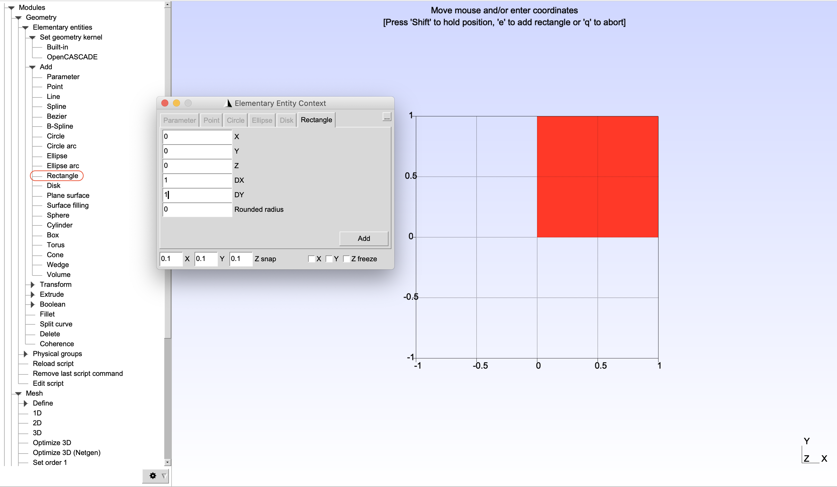
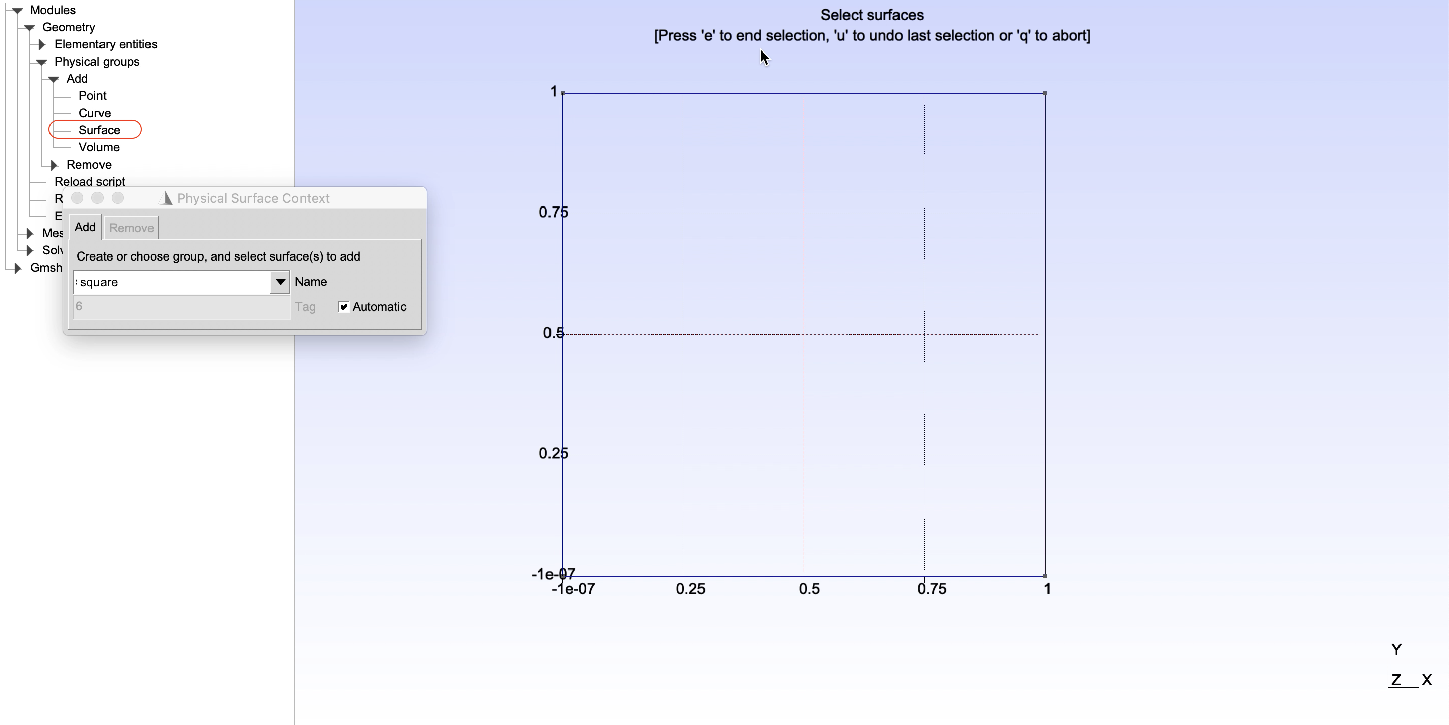
Modules -> Geometry -> Elementary entities -> Add can be used to create wide variaty of 2D geometries. For example, points and lines can be used to create a L-shape surface.Physical groups are used to define groups of entities that later will be given attributes including inputs of names, material properties, loading conditions, contrainsts, etc. These attributes will be read by MoFEM during analysis.
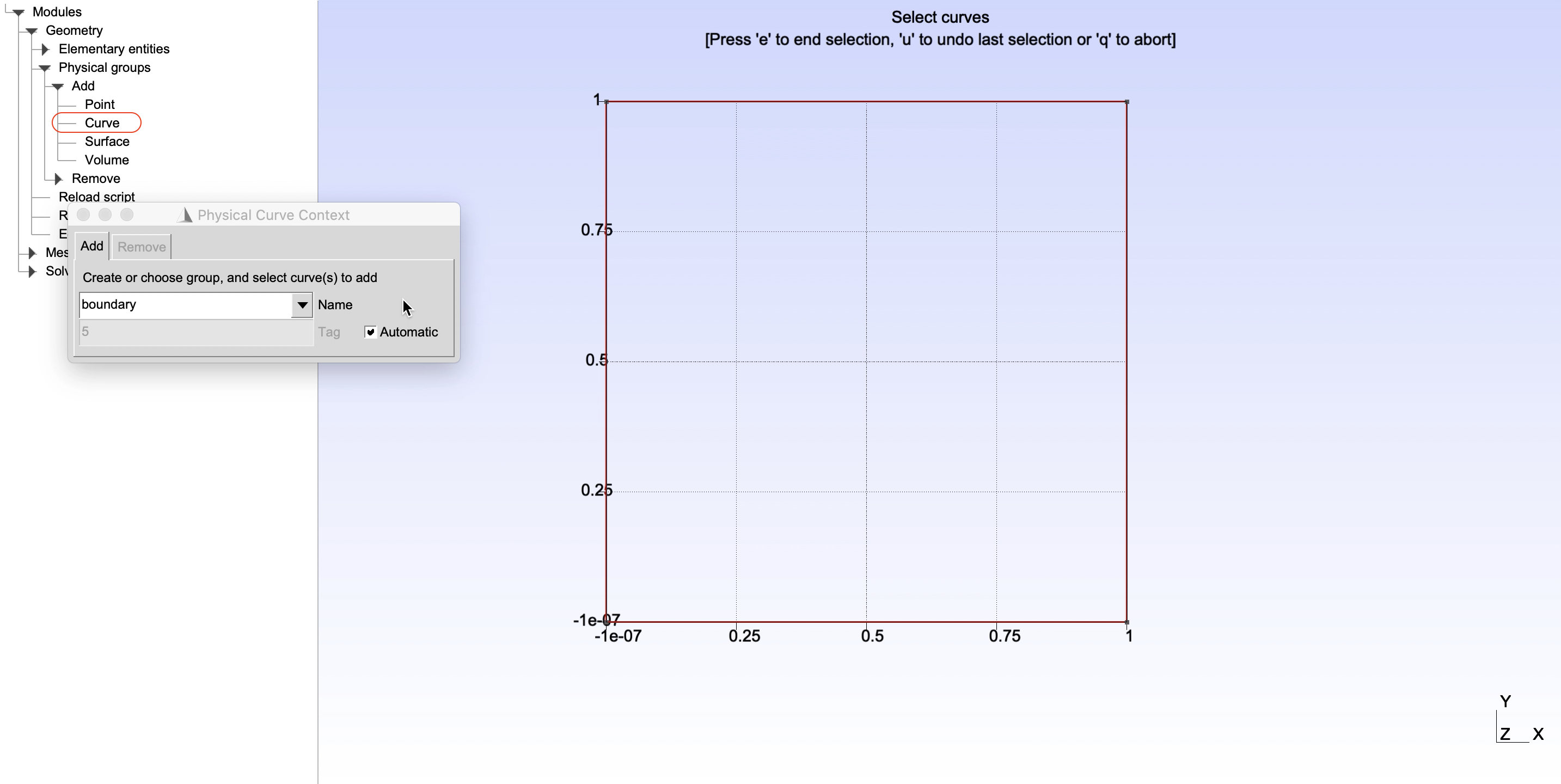
As a demonstration, in this part, physical groups of edges and surface of the 2D square will be defined as shown in Figure 2 and Figure 3. It can be done by choosing, from the left panel, Modules -> Geometry -> Physical groups -> Add -> Surface/Curve. Then give name of a physical groups in the box Name, select entities to add to the corresponding groups and finally press e to end the selection.
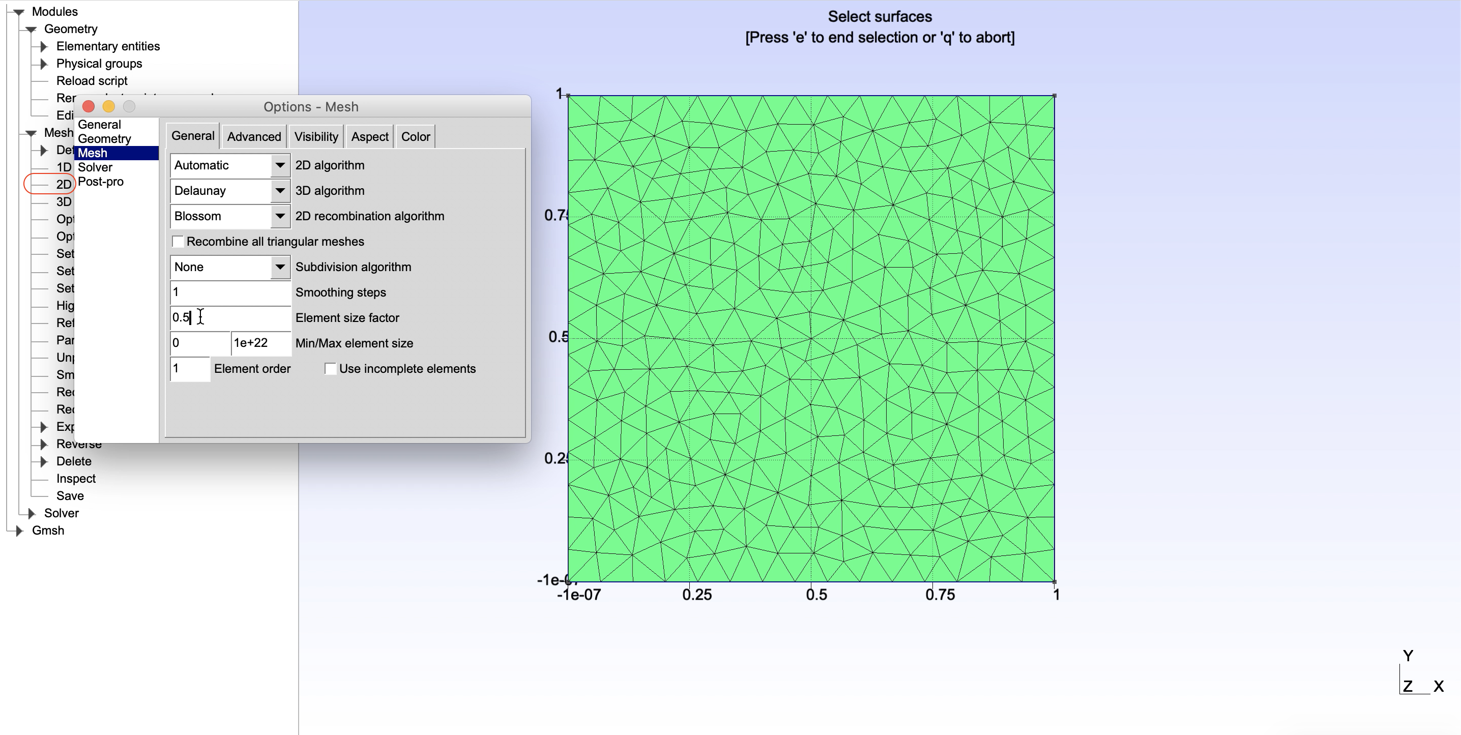
Go to Tools -> Options -> Mesh, in the General tab, choose the meshing algorithms and change the element size factor, e.g. 0.5 as shown in Figure 4, then close the window. To create the 2D mesh for the square, on the left panel, choose Modules -> Mesh -> 2D.
A preferred mesh format that will be exported is MED. This can be done by go to File -> Export ... then choose the file type Mesh - MED (*.med) and give a file name, e.g. square.med
The mesh created by Gmsh in the previous step is not immediately compatible in a MoFEM analysis. We would need to provide additional information to the defined physical groups (blocksets) and convert the mesh to *.h5m format. We can do it by the following steps
*.h5m format using read_med toolAs mentioned above, the mesh created by Gmsh does not contains attributes that may be needed for some tasks for analysis in MoFEM, e.g. blockset with a specific name to add material properties, boundary conditions, loadings. We need to know the exact ID of the physical group (blockset) in the MED file in order to add attributes to that blockset, we can check the IDs by running the read_med as follows
which would show that the defined physical groups square and boundary have the ID of 1 and 2, respectively, as in the following output message
We would then use these IDs in the config file, named square.config, as below
where [block_1] and [block_2] use the blockset IDs in the MED mesh which cannot be changed. Meanwhile, id=100 and id=110 are the IDs, specified by user at this step, of the new blocksets that will be created in the next step. The remaining of each block are the attributes that will be added, e.g. material properties or even just a blockset with a specific name that will be used in some MoFEM program.
Once the MED file and config file are ready, the final mesh file in *.h5m format that contains necessary information and can read by MoFEM can be generated by running the command below
After running this command, the square.h5m file will be created and the main part of the output message would look like this
As can be seen, along with the original blocksets 1 and 2, the output mesh square.h5m now contains the two new blocksets 100 and 110 with the names MAT_ELASTICSET and BOUNDARY_CONDITION, respectively, with additional attributes. Using the same concept, more blocksets for different purposes can be added to the mesh.
Once the final square.h5m mesh is generated, it can be used directly as an input in MoFEM programs, e.g. SCL-1: Poisson's equation (homogeneous BC).