v0.14.0
COR-0: Mixed formulation and integration on skeleton (h-adaptivity)

Set by step example how to implement mix finite element and do hp-adaptivity

Here we present general procedure applied to h-adaptivity of mix problem. MoFEM is generic finite element code capable of solving problems from magnetics, mechanics of fluids and solids, and as a result of this operates on necessary complex data structures able to carry abstract problems. If you master this example, applying the same approach, you will be able to implement in similar way other problems, for instance, Discontinuous Galerkin Method, or thermo-mechanical coupled problem.

In this tutorial, we show how to implement h-adaptivity for mix transport formulation for stationary transport/heat-conduction problem (The Poisson equation). We focus on h-adaptivity, however, this implementation allows running problem with the arbitrary order of approximation and extension to p-/hp-adativity is possible.

Code relevant to this tutorial could be found in Mix transport element module. Plane source code for main program is available under link h_adaptive_transport.cpp, whereas main class implementation of finite element and finite element operators is available here MixTransportElement.hpp.

MoFEM is built on three pillars, PETSc library which manages abstraction related to the algebraic system of equations and delivers interface to several solvers, mesh-oriented database (MoAB) which manages complexities related to mesh topology and delivers various format readers and Boost library which through multi-indices manages access to containers with MoFEM data structures.

MoFEM handles complexities related to finite element method, degrees of freedom, approximation spaces and base functions. It provides tools and structures for implementation classical and nonclassical finite element codes and can handle linear, nonlinear and time dependent problems.

Here we are considering a problem

\[ A_{ij} \sigma_j + u_{,i} = 0 \; \textrm{on} \; \Omega \\ \sigma_{i,i} = f \; \textrm{on} \; \Omega \]

where first equation is a physical (constitutive) equation and tensor \(A_{ij}\) express material properties, for example, if \(A_{ij}\) is a diagonal matrix with single constant on diagonal we have an isotropic material. The second equation is conservation equation, which expresses law that mass or energy can ot be created or destroyed (close system).

Multiplying the constitutive equation by a test field \(\tau\) and integrating by parts over \(\Omega\) (taking into account the inhomogeneous Dirichlet boundary condition), we obtain

\[ \int_\Omega A_{ij}\sigma_j \tau_i \textrm{d}x - \int_\Omega u \tau_{i,i} \textrm{d}x = \int_{\Gamma_\textrm{u}} \overline{u} \tau_{i} n_i \textrm{d}\Gamma ,\quad \forall \boldsymbol\tau \in H(\textrm{div},\Omega) \]

while from the equilibrium equation by multiplying by test field \(v\) we obtain

\[ \int_\Omega \sigma_{i,i}v \textrm{d}x = \int_\Omega f v \textrm{d}x, \quad \forall v \in L^2(\Omega). \]

Before we look into implementation details, you can run simple example

cd basic_finite_elements/mix_transport
mpirun -np 2 ./h_adaptive_transport \
-my_file l-shape.msh -meshsets_config bc.cfg \
-my_order 1 -nb_levels 5 2>&1 | tee log_order1

where

  • -np 2 indicate number of processors
  • -my_file l-shape.msh name of the mesh file
  • -meshsets_config bc.cfg name of file with boundary conditions
  • -my_order 1 set approximation order (0,1,2,..)
  • -nb_levels 5 set number of mesh refinement level driven by approximation error

Above code produces output files, out_0.h5m, out_1.h5m, ... where number of files is dependent on number of refinement levels. You can convert those files to VTK format running script

../nonlinear_elasticity/do_vtk.sh out_*.h5m

and post-process results in ParaView http://www.paraview.org.

As result of post-processing in ParaView we have created following output

h-adaptivity
Flux singularity
Convergence plot

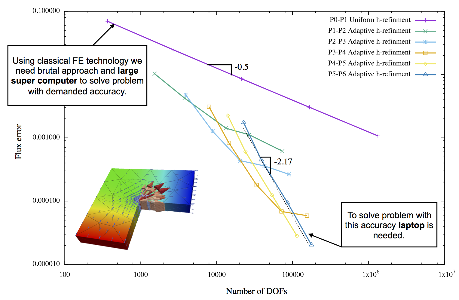
You can note that subsequent mesh refinement reduces error and make it more uniformly distributed through the mesh. You can also observe that mesh is getting denser at the corner where singularity is located.

Todo:
Should be implemented and tested problem from this article [24]. In this paper analytical solution is available, allowing to tested efficiency of evaluated error. You are very welcome to improve that documentation.

Explaining mesh BitRefLevel

MoFEM::BitRefLevel is a generic tool which allows working on several overlapping meshes, partially sharing entities and topology. In the context of this problem, we would use it to create and work with a hierarchy of mesh refinement.

For each entity in a database (vertex, edge, triangle, quad, ..., tetrahedra, brick, prism, ...) we attach bit tag, i.e. MoFEM::BitRefLevel. Using that tag we can make selections of entities and other operations on meshes.

It will be easier to understand if you look at the figure below

Mesh bit refinement levels (Example)

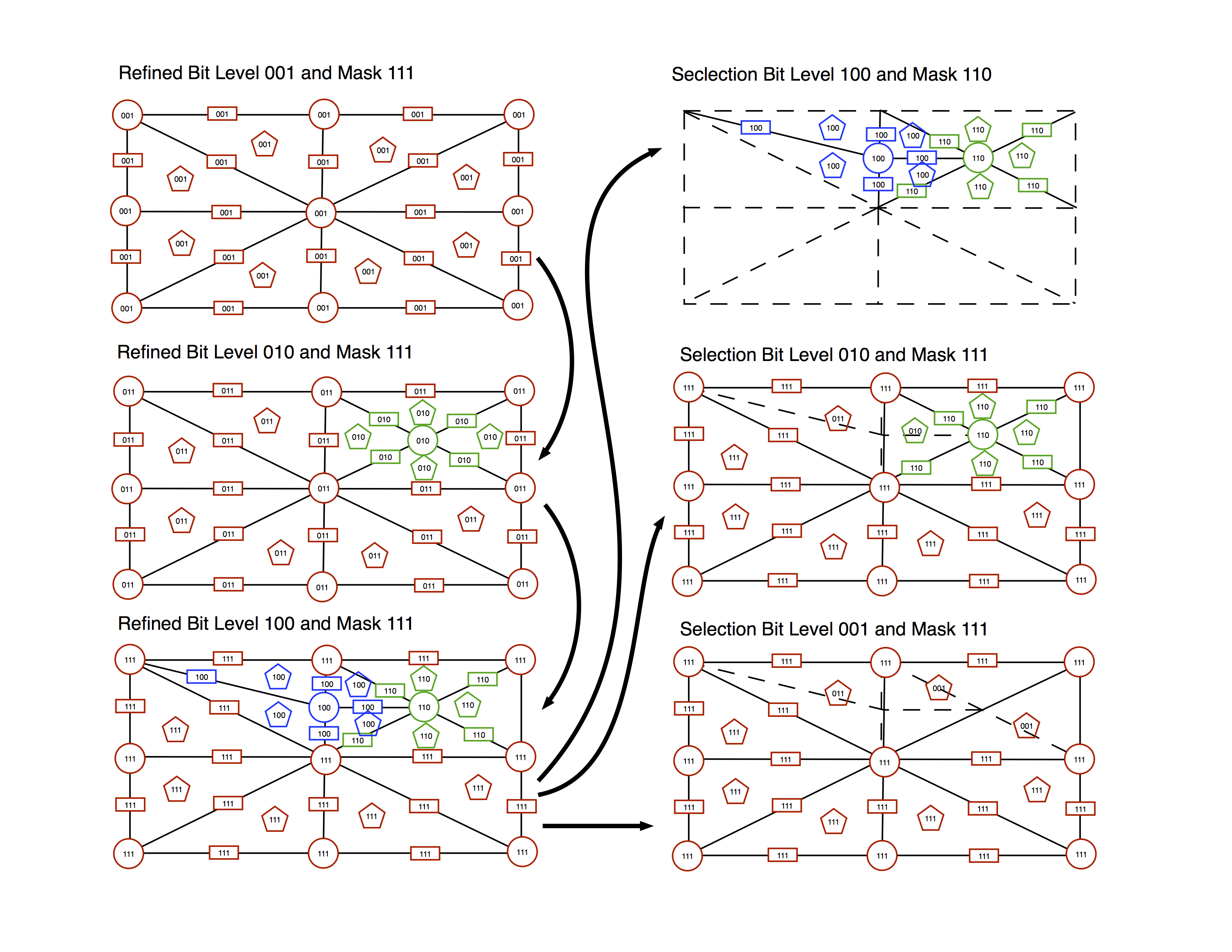
Imagine that we load the mesh with the topology like in the top-left figure. We seed the mesh (MoFEM::Interface::seed_ref_level) by tagging each entity with the first bit on, i.e. 001.

Next, we refine by splitting one of the edges, see middle-left figure. You can understand that as edge-splitting-mesh refinement, see [63]. As the result of this mesh refinement, new vertex in the middle of the edge is created, four new edges and four triangles. The remaining of mesh entities is part of old and new mesh level. As a consequence, entities which are shared between the second mesh and first mesh have two bites on, i.e. 011, since those are coexisting on two meshes. New entities have the only second bit on, i.e. 010.

In the next step, we made third mesh refinement. The procedure repeats, we have some new entities which have the only third bit on, i.e. 100, some entities are shared between refinement second and third, those have third and a second bit on, i.e. 110, and some entities are shared between all refinement levels, i.e. 111. In current implementation, we assume that user would not have more than 32 refinement levels. However bit squashing and bit level deletion allows form deep (more than 32) mesh refinements.

Physically all three meshes overlap, we do not delete overlapped entities or create new whole mesh each time. It is the reason behind that since we like to transfer data between different refinement levels without the redundancy and unnecessary copying and communication between processors if the mesh is distributed.

Now we present examples of mesh selections; you can practically do everything that you do with bits, see https://en.wikipedia.org/wiki/Bitwise_operation#Bit_shifts. For example;

  • Setting bit 100 and mask 110 we can select all entities which were created during second and third refinement level, see top-right figure.
  • Setting bit 010 and mask 111 we can get entities only which belong to the second refinement, see middle-right figure.
  • Setting bit 001 and mask 111 we can get entities only which are belong initial mesh, see the figure in the bottom right corner.

That allows to project data between meshes, do calculations on the part of the mesh, to introduce cracks, make topological changes like face flipping. Note that problem below is defined for particular bit levels. See link Get entities and adjacencies for details how to get entities and adjacent by bit refinement levels.

Setting up problem

We consider the problem which potentially can have complex geometry and a non-trivial set of boundary conditions. Here we use Gmsh (see http://gmsh.info) to generate the mesh. In this section, we focus attention on how to read mesh file and how to apply some arbitrary boundary conditions on that mesh.

The first step is to create mesh database, where information about the problem is stored. We create MoAB (see http://ftp.mcs.anl.gov/pub/fathom/moab-docs/) instance and interface to it

moab::Core mb_instance; ///< Create database
moab::Interface& moab = mb_instance; ///< Create interface to database

Once we have created mesh database, we get from command line name of file which we like to load

PetscBool flg = PETSC_TRUE; ///< Is true of option is set in line command
char mesh_file_name[255]; ///< File name
CHKERR PetscOptionsGetString(PETSC_NULL,PETSC_NULL,"-my_file",mesh_file_name,255,&flg);

where here we are using PETSc function to do that, see http://www.mcs.anl.gov/petsc/petsc-current/docs/manualpages/Sys/PetscOptionsGetString.html for more details. Having mesh file name, we can load mesh, created in Gmsh, to database

const char *option;
option = "";
CHKERR moab.load_file(mesh_file_name, 0, option);

MoFEM can read various file format in this example we are using mesh from Gmsh, where example file geometry is stored in file l-shape.geo and mesh is in l-shape.msh. For more details about file formats please look into MoAB documentation.

Creating MoFEM database to store information about fields, finite elements and problem, we link it to MOAB database and create interface to manage data

MoFEM::Core core(moab); ///< Create database
MoFEM::Interface& m_field = core; ///< Create interface to database

In file \erf l-shape.msh following geometry and mesh is described

Blocksets and GMesh mesh

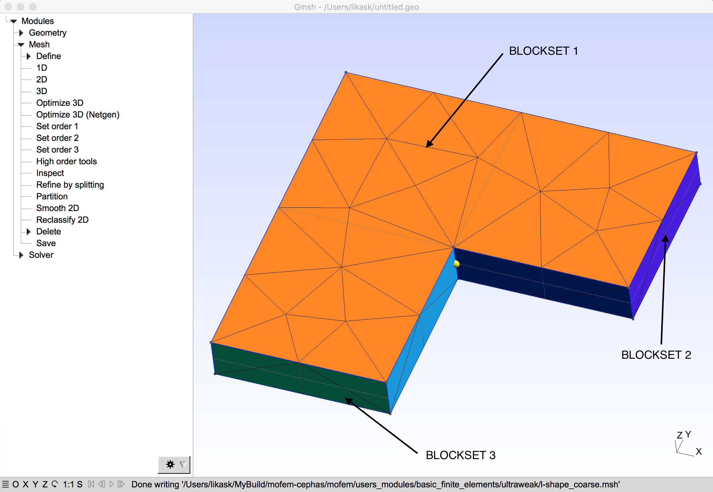
where as result of reading of that mesh into MoFEM database, following information is printed on the screen

read cubit meshset 12682136550675316737 type BLOCKSET msId 2
read cubit meshset 12682136550675316738 type BLOCKSET msId 3
read cubit meshset 12682136550675316741 type BLOCKSET msId 1

The output to the screen indicates that three BLOCKSETs are available. Those BOLCKSETs are interpreted as Physical Volume and Physical Surfaces which were created in Gmsh. User can create more sophisticated geometry or use more complex set of boundary conditions. Interpretation of BLOCKSETs is a matter of separate config file, which describes problem specific types of boundary conditions.

The interpretation of BLOCKSETs is done by the meshset config file bc.cfg,

According to that file, BLOCKSET 3 is set to be NODESET 1001 where temperature is applied \(u=0\, x \in \partial \Omega_u\) and BLOCKSET 2 is set to be SIDESET 1002 where flux is applied \(n_i\sigma_i = 1\, x \in \partial \Omega_\sigma\). On BLOCKSET 1 is the domain \(\Omega\) where problem is defined.

In the above example, temperature type, heat flux type and temperature volume are used. This is a matter of interpretation as well, we are using this convention to be consistent with other meshing programs like CUBIT where boundary conditions like that can be set directly. However, MoFEM user can set own types and attach own interpretation if needed.

Boundary condition meshsets are managed in MoFEM by MoFEM::MeshsetsManager interface. Using that interface user can access information about boundary conditions and add a new one. All modules and software components using that interface can easily share information through it. To get access to interface, user needs to query MoFEM for it, as follows

MoFEM::MeshsetsManager *meshsets_manager_ptr; //< Click on class to see more details
CHKERR m_field.getInterface(meshsets_manager_ptr);

using interface we can read file bc.cfg, parse it and add boundary conditions. All this is automatized for user convenience and done with single interface method

CHKERR meshsets_manager_ptr->setMeshsetFromFile(); //<- Click on function to see more details

In general, user can query about range of interfaces giving access to specific tools. In this example we are using two types of interfaces, one to manage BLOCKSETs, i.e. MoFEM::MeshsetsManager and another for refining meshes, i.e. MoFEM::MeshRefinement.

Note
MoFEM uses interfaces to do particular tasks, could have one or more interfaces for the same task, which differs in complexity, one is simple to do basic operation while another can be for advanced users. It can have different versions of the interface. We design MoFEM like that to have a structure which can adapt in time to new technologies and programmers need.
Note that all commands return an error code and after each function, an error code is checked, in a case of the error, appropriate information is printed during execution time. It is important to follow that rule, of checking the error code, it simplifies code debugging and bug reporting.

Solving problem and calculating matrices and vectors

We start with calculating initial problem on mesh created with Gmsh. The problem is broken down into several stages, implementation of a mix transport problem is in ExampleMix which is derived from MixTransport::MixTransportElement.

Note
We have the hierarchy of classes (structures), some of them are generic thus are part of MoFEM namespace and are implemented in the core library. Others are generic for a particular problem, for example, mix transport formulation (MixTransport::MixTransportElement) is implemented in user modules. And finally, some classes (ExampleMix) are for very specific example, where some close solution is needed.

In class MixTransport::MixTransportElement all operators for evaluating matrices, the right-hand side vector, error evaluation are implemented. Moreover methods for declaring and defining fields, finite elements and problems are added. This class could be used by other users, solving similar problems.

In derived class ExampleMix, particular functions for given transport problem with h-adaptivity are implemented. The method handles specific boundary conditions for this example.

The general procedure to solve problem looks like follows

BcFluxMap bc_flux_map;
ExampleMix ufe(m_field,bc_flux_map);
// Initially calculate problem on coarse mesh
CHKERR ufe.addFields("VALUES","FLUXES",order);
CHKERR ufe.addFiniteElements("FLUXES","VALUES");
// Set boundary conditions
CHKERR ufe.addBoundaryElements(ref_level);
CHKERR ufe.buildProblem(ref_level);
CHKERR ufe.createMatrices();
CHKERR ufe.solveLinearProblem();
CHKERR ufe.calculateResidual();
CHKERR ufe.evaluateError();
CHKERR ufe.destroyMatrices();
CHKERR ufe.postProc("out_0.h5m");

such procedure will look very similar to other problems, where we set-up problem, apply boundary conditions, solve problem and postprocess results.

Some MoFEM functions and philosophy of building problem are explained in minimal_surface_equation, please look into that document for further explanation.

Adding fields to the database (ufe.addFields)

In MixTransport::MixTransportElement::addFields, we declare and define fields and add entities to those on which given field is spanning.

MoFEMErrorCode MixTransport::MixTransportElement::addFields(const std::string &values,const std::string &fluxes,const int order) {
//Fields
//meshset consisting all entities in mesh
EntityHandle root_set = mField.get_moab().get_root_set();
//add entities to field
CHKERR mField.add_ents_to_field_by_type(root_set,MBTET,fluxes);
CHKERR mField.add_ents_to_field_by_type(root_set,MBTET,values);
CHKERR mField.set_field_order(root_set,MBTET,fluxes,order+1);
CHKERR mField.set_field_order(root_set,MBTRI,fluxes,order+1);
CHKERR mField.set_field_order(root_set,MBTET,values,order);
}

Note that in the first two lines we declare two fields FLUXES and VALUES. We define fields, by setting space to HDIV and L2, respectively. The fourth argument in functions MoFEM::Interface::add_field sets number of coefficients. Since we have vector and scalar field, number of coefficients is 1. If for example we would like to have second rank field for HDIV space and vector field for L2 space, number of coefficients would be three. Note that in general case you can set the field on part of the mesh and on some part it could be 3d field, 2d or 1d.

Function MoFEM::Interface::add_ents_to_field_by_TETs adds entities to a field, in this case, we like to solve the problem on whole mesh, so all entities from root meshset are added. Since we span that field on tetrahedra and all lower entities field is in 3d. The dimension of field is dictated by a dimension of entities.

Adding elements to the database (ufe.addFiniteElements)

In the following part of the code we declare finite elements, implementation of elements is done separately. By definition of finite elements, we are simply telling code on what fields given finite element operates. Domain of elements, i.e. entities on which elements integrate operators could be declared on the part of the mesh where the field is given. If you declare element on entities on which fields is no spanning, that element will have zero number of degrees of freedom.

In this example, we have four kinds of finite elements MIX, MIX_SKELETON, MIX_BCVALUE and MIX_BCFLUX.

  • MIX finite element is used to integrate over volume; it allows us to calculate stiffness matrix and the right-hand side vector.
  • MIX_SKELETON finite element is used to integrate over the skeleton, i.e. faces between elements. We are using it to calculate jumps of the values to evaluate the solution error.
  • MIX_BCVALUE finite element is used to integrate over faces where Dirichlet (natural) boundary conditions are declared. The values integrated on that element are assembled into the right-hand side vector.
  • MIX_BCFLUX is the finite element to calculate degrees of freedom where flux boundary conditions are declared. This element works on faces. Note that in mix transport formulation Neumann boundary conditions are essential.
const std::string &fluxes_name,
const std::string &values_name
) {
// Set up volume element operators. Operators are used to calculate components
// of stiffness matrix & right hand side, in essence are used to do volume integrals over
// tetrahedral in this case.
// Declare element "MIX". Note that this element will work with fluxes_name and
// values_name. This reflect bilinear form for the problem
// Define element
// Declare finite element to integrate over skeleton, we need that to evaluate error
// Define element
CHKERR mField.modify_finite_element_add_field_row("MIX_SKELETON",fluxes_name);
CHKERR mField.modify_finite_element_add_field_col("MIX_SKELETON",fluxes_name);
CHKERR mField.modify_finite_element_add_field_data("MIX_SKELETON",fluxes_name);
// In some cases you like to use HO geometry to describe shape of the body, curved edges and faces, for
// example body is a sphere. HO geometry is approximated by a field, which can be hierarchical, so shape of
// the edges could be given by polynomial of arbitrary order.
//
// Check if field "mesh_nodals_positions" is declared, and if it is add that field to data of finite
// element. MoFEM will use that that to calculate Jacobian as result that geometry in nonlinear.
if(mField.check_field(mesh_nodals_positions)) {
CHKERR mField.modify_finite_element_add_field_data("MIX",mesh_nodals_positions);
CHKERR mField.modify_finite_element_add_field_data("MIX_SKELETON",mesh_nodals_positions);
}
// Look for all BLOCKSET which are MAT_THERMALSET, takes entities from those BLOCKSETS
// and add them to "MIX" finite element. In addition get data from that meshset
// and set cOnductivity which is used to calculate fluxes from gradients of concentration
// or gradient of temperature, depending how you interpret variables.
// cerr << *it << endl;
Mat_Thermal temp_data;
CHKERR it->getAttributeDataStructure(temp_data);
setOfBlocks[it->getMeshsetId()].cOnductivity = temp_data.data.Conductivity;
setOfBlocks[it->getMeshsetId()].cApacity = temp_data.data.HeatCapacity;
CHKERR mField.get_moab().get_entities_by_type(
it->meshset,MBTET,setOfBlocks[it->getMeshsetId()].tEts,true
);
CHKERR mField.add_ents_to_finite_element_by_TETs(
setOfBlocks[it->getMeshsetId()].tEts,"MIX"
);
Range skeleton;
CHKERR mField.get_moab().get_adjacencies(
setOfBlocks[it->getMeshsetId()].tEts,2,false,skeleton,moab::Interface::UNION
);
skeleton,MBTRI,"MIX_SKELETON"
);
}
// Declare element to integrate natural boundary conditions, i.e. set values.
// Define element
CHKERR mField.modify_finite_element_add_field_row("MIX_BCVALUE",fluxes_name);
CHKERR mField.modify_finite_element_add_field_col("MIX_BCVALUE",fluxes_name);
CHKERR mField.modify_finite_element_add_field_data("MIX_BCVALUE",fluxes_name);
CHKERR mField.modify_finite_element_add_field_data("MIX_BCVALUE",values_name);
if(mField.check_field(mesh_nodals_positions)) {
CHKERR mField.modify_finite_element_add_field_data("MIX_BCVALUE",mesh_nodals_positions);
}
// Declare element to apply essential boundary conditions.
// Define element
if(mField.check_field(mesh_nodals_positions)) {
CHKERR mField.modify_finite_element_add_field_data("MIX_BCFLUX",mesh_nodals_positions);
}
}

Function MoFEM::Interface::add_finite_element adds the element of given name to the database, the second argument indicates that if the element of such name already exists do not throw the error. When the second argument is not given default behaviour is that error is thrown if the element already exists.

Function MoFEM::Interface::modify_finite_element_add_field_row, MoFEM::Interface::modify_finite_element_add_field_col and MoFEM::Interface::modify_finite_element_add_field_data define on what fields given element operates. You can think that this corresponds how you define the bilinear form for your operator, what is the first and second argument. Also, you specify data, for example, permeability could be given as a separate field which needs to be evaluated at integration points to assemble matrix. In that case you add that information using MoFEM::Interface::modify_finite_element_add_field_data.

Function MoFEM::Interface::add_ents_to_finite_element_by_type adds tetrahedral and triangles to given element respectively. You can think about tetrahedral and triangles as domains on which you perform the integration. Note that field can be spanned on tetrahedral (3d entities) but you can integrate on triangles, then on such element trace of field on the triangle is available from that element.

Note part of the code

which iterates over all BLOCKSETs on which MAT_THERMALSET is defined, then it gets information about material parameters and range of tetrahedral entities in that block. Next, it adds those tetrahedral to MIX finite element. In addition, it takes all adjacent triangles to tetrahedra and adds those entities to MIX_SKELETON finite element.

Adding elements to MIX_BCVALUE and MIX_BCFLUX is implemented in the next section. In above code, those finite elements are only declared and defined, but not yet implemented. Declaration, definition and implementation are independent of each other. You can use two different implementations of the same element.

Adding boundary elements to the database (ufe.addBoundaryElements)

In ExampleMix::addBoundaryElements, loop over boundary BLOCKSETs is made to get triangles in that BLOCKSET. Then appropriate triangles are added to MIX_BCVALUE and MIX_BCFLUX

MoFEMErrorCode ExampleMix::addBoundaryElements(BitRefLevel &ref_level) {
Range tets;
CHKERR mField.getInterface<BitRefManager>()->getEntitiesByTypeAndRefLevel(ref_level,BitRefLevel().set(),MBTET,tets);
Skinner skin(&mField.get_moab());
Range skin_faces; // skin faces from 3d ents
CHKERR skin.find_skin(0,tets,false,skin_faces);
// note: what is essential (dirichlet) is natural (neumann) for mix-FE compared to classical FE
Range natural_bc;
Range tris;
CHKERR it->getMeshsetIdEntitiesByDimension(mField.get_moab(),2,tris,true);
natural_bc.insert(tris.begin(),tris.end());
}
HeatFluxCubitBcData mydata;
CHKERR it->getBcDataStructure(mydata);
if(mydata.data.flag1==1) {
Range tris;
CHKERR it->getMeshsetIdEntitiesByDimension(mField.get_moab(),2,tris,true);
bcFluxMap[it->getMeshsetId()].eNts = tris;
bcFluxMap[it->getMeshsetId()].fLux = mydata.data.value1;
// cerr << bcFluxMap[it->getMeshsetId()].eNts << endl;
// cerr << bcFluxMap[it->getMeshsetId()].fLux << endl;
}
}
Range essential_bc = subtract(skin_faces,natural_bc);
Range bit_tris;
CHKERR mField.getInterface<BitRefManager>()->getEntitiesByTypeAndRefLevel(ref_level,BitRefLevel().set(),MBTRI,bit_tris);
essential_bc = intersect(bit_tris,essential_bc);
natural_bc = intersect(bit_tris,natural_bc);
CHKERR mField.add_ents_to_finite_element_by_type(essential_bc,MBTRI,"MIX_BCFLUX");
CHKERR mField.add_ents_to_finite_element_by_type(natural_bc,MBTRI,"MIX_BCVALUE");
// CHKERR mField.add_ents_to_finite_element_by_type(skin_faces,MBTRI,"MIX_BCVALUE");
}

Note that, at the end of the above code, the skin from full mesh is taken, i.e. triangle elements on boundary of meshet. Then, triangles on the boundary (skin) on which values or fluxes are not set are used to set zero-flux boundary condition.

Note
For standard finite element formulation, boundary condition on fluxes is natural, so if you have zero flux on the boundary, you have zero value for DOFs on the right-hand side vector. In essence, you do nothing to enforce zero flux. This is not the case here.

In addition, function

MoFEMErrorCode ExampleMix::getBcOnValues(
const EntityHandle ent,
const double x,const double y,const double z,
double &value) {
value = 0;
}

and

MoFEMErrorCode ExampleMix::getBcOnFluxes(
const EntityHandle ent,
const double x,const double y,const double z,
double &flux) {
if(lastEnt==ent) {
flux = lastFlux;
} else {
flux = 0;
for(BcFluxMap::iterator mit = bcFluxMap.begin();mit!=bcFluxMap.end();mit++) {
Range &tris = mit->second.eNts;
if(tris.find(ent)!=tris.end()) {
flux = mit->second.fLux;
}
}
lastEnt = ent;
lastFlux = flux;
}
}

are implemented. Those functions are used to evaluate values and boundary conditions at integration points. For more details how those functions are used look into MixTransport::MixTransportElement::OpRhsBcOnValues and MixTransport::MixTransportElement::OpEvaluateBcOnFluxes, those classes are implementations of operations on particular elements which are later explained.

Declaring and building problem (ufe.buildProblem)

Once fields and finite elements are declared and defined, we build/rebuild data structures carrying information needed to do the analysis. Note that function below is general, takes into account that problem could be built on several refinement levels, and if only the necessary part of structures if rebuild in subsequent mesh refinements.

The mesh MoFEM::BitRefLevel and related details with mesh refinement are described in the following sections. Here we focus only on declaring, building and partitioning problem for parallelized calculations.

MoFEM can work on partitioned meshes and parallel algebra and calculations. However, here we assume that mesh is the same on all processors, only calculations, matrices and vectors are distributed.

//build field
// get tetrahedrons which has been build previously and now in so called garbage bit level
Range done_tets;
CHKERR mField.getInterface<BitRefManager>()->getEntitiesByTypeAndRefLevel(
BitRefLevel().set(0),BitRefLevel().set(),MBTET,done_tets
);
CHKERR mField.getInterface<BitRefManager>()->getEntitiesByTypeAndRefLevel(
BitRefLevel().set(BITREFLEVEL_SIZE-1),BitRefLevel().set(),MBTET,done_tets
);
// get tetrahedrons which belong to problem bit level
Range ref_tets;
CHKERR mField.getInterface<BitRefManager>()->getEntitiesByTypeAndRefLevel(
ref_level,BitRefLevel().set(),MBTET,ref_tets
);
ref_tets = subtract(ref_tets,done_tets);
CHKERR mField.build_finite_elements("MIX",&ref_tets,2);
// get triangles which has been build previously and now in so called garbage bit level
Range done_faces;
CHKERR mField.getInterface<BitRefManager>()->getEntitiesByTypeAndRefLevel(
BitRefLevel().set(0),BitRefLevel().set(),MBTRI,done_faces
);
CHKERR mField.getInterface<BitRefManager>()->getEntitiesByTypeAndRefLevel(
BitRefLevel().set(BITREFLEVEL_SIZE-1),BitRefLevel().set(),MBTRI,done_faces
);
// get triangles which belong to problem bit level
Range ref_faces;
CHKERR mField.getInterface<BitRefManager>()->getEntitiesByTypeAndRefLevel(
ref_level,BitRefLevel().set(),MBTRI,ref_faces
);
ref_faces = subtract(ref_faces,done_faces);
//build finite elements structures
CHKERR mField.build_finite_elements("MIX_BCFLUX",&ref_faces,2);
CHKERR mField.build_finite_elements("MIX_BCVALUE",&ref_faces,2);
CHKERR mField.build_finite_elements("MIX_SKELETON",&ref_faces,2);
//Build adjacencies of degrees of freedom and elements
//Declare problem
//set refinement level for problem
// Add element to problem
// Boundary conditions
//build problem
ProblemsManager *prb_mng_ptr;
CHKERR mField.getInterface(prb_mng_ptr);
CHKERR prb_mng_ptr->buildProblems();
//mesh partitioning
//partition
CHKERR prb_mng_ptr->partitionProblem("MIX");
CHKERR prb_mng_ptr->partitionFiniteElements("MIX");
//what are ghost nodes, see Petsc Manual
CHKERR prb_mng_ptr->partitionGhostDofs("MIX");
}

In the above code, several key functions are used. Function MoFEM::Interface::build_fields builds field data structure by construction degrees of freedom on each entity on which given field is spanning. For example, for L2 space, DOFs are only on tetrahedra which were added to the field. For H-div space is the more complex case, degrees of freedom are associated with triangles and tetrahedra, but a number of degrees of each type of entity depend on approximation order, for details look to [1].

At that point, field structure is created including DOFs on entities. Such structure can carry information about approximation order and values of a field. For example, you can do algebraic operations on field values directly mofem_field_algebra.

No indices are attached to DOFs since indices depend on a number of processors on which solution is carried on, partitioning method or directly type of problem which you like to solve.

Function MoFEM::Interface::build_finite_elements is used to build data structure. You can note that, in the above code, in subsequent mesh refinements, elements are added to the database, no whole base is rebuilt from scratch. At that point, information about degrees of freedom of fields acting on the element is aggregated. Finite element is problem independent.

Once fields and finite element structures are built, we can build problem. Domain of the problem, its size and structure of the matrix are uniquely defined by finite elements and fields on which element operates. First, a problem is declared using MoFEM::Interface::add_problem, where the argument of the function is the name of the problem which we like to add. Next we define problem, by setting finite elements, this is done using function MoFEM::Interface::modify_problem_add_finite_element where elements are added to the problem.

To build problem, we need to set MoFEM::BitRefLevel to the problem. In short MoFEM::BitRefLevel allows selecting a refined mesh on which we like to solve our problem. The details and unique flexibility of MoFEM::BitRefLevel are explained in Explaining mesh BitRefLevel.

Note
Declaration, definition and building of data structures, are independent of each other. We can first declare fields, finite elements and problems, then define at the end build data structures. Implementation of a finite element is independent of its definition.

Having all those stages done, at that point, structure of algebraic equations emerging from problem definition, finite elements, fields and domains on which finite elements and fields operate. That defines the structure of sparse matrix and structure of parallel vectors which ghost values.

Note
MoFEM utilizes properties of approximation spaces, knowing space of approximation field, we know how DOFs are distributed on the mesh. With information about the bilinear form, which is set in the definition of a finite element, we can build adjacencies between DOFs. At last, with the definition of a problem, i.e. set of finite elements in the problem, we can build unique enumeration of DOFs and build the system of algebraic equations. Using spaces (L2, H1, H-DIV, H-CURL) and their properties, we build a system of a data structure which abstracts and general.

Create vectors and matrices (ufe.createMatrices)

At that point, we have defined and partitioned problem and that is enough to construct distributed matrices and vectors. The sparsity of the matrix, adjacencies and other bookkeeping operations are handled by MoFEM and PETSc.

Functions and use of below code have been explained earlier in minimal_surface_equation;

CHKERR mField.getInterface<MatrixManager>()->createMPIAIJWithArrays<PetscGlobalIdx_mi_tag>("MIX",&Aij);
CHKERR mField.getInterface<VecManager>()->vecCreateGhost("MIX",COL,&D);
CHKERR mField.getInterface<VecManager>()->vecCreateGhost("MIX",COL,&D0);
CHKERR mField.getInterface<VecManager>()->vecCreateGhost("MIX",ROW,&F);
}

Assemble and solve

At this point, we have all data structures necessary to solve the problem. Now we focus attention on the implementation of finite element instances and solution procedure. In essence, we need to assemble matrices and vectors, enforce constraints, solve a linear system of equations and post-process results.

Finite element instances

Definition of the finite element allows building the structure (adjacency) of the matrix, however, assemble (calculate) matrix we need finite element class implementation and its instance which will do the work. MoFEM allows implementing finite element at a low level, however, except special cases, a generic finite element class implementations can be used, where some operations like calculation of Jacobian, face areas and normals are implemented. Generic finite element classes enable us to focusses attention on the implementation of the bilinear form and its algebraic representation. That is numerical integration and evaluation of physical equations, evaluation of base functions and fields. The implementation of generic finite element is done by user data operators, see tutorials FUN-0: Hello world and COR-2: Solving the Poisson equation. Class of user data operator is inherited, and problem specific application is by function overloading. From user data operator class, we have access to base functions, integration points, local and global indices and values of DOFs. etc. UserDataOperator is run for entities on the element, on which approximation base is constructed.

In MixTransport::MixTransportElement class we create two generic finite element instances, i.e. MixTransport::MixTransportElement::MyVolumeFE and MixTransport::MixTransportElement::MyTriFE.

int getRule(int order) { return 2*order+1; };
};
MyVolumeFE feVol; ///> Instance of volume element
int getRule(int order) { return 2*order+1; };
};
MyTriFE feTri; ///< Instance of surface element

Those two finite element classes have method MoFEM::ForcesAndSourcesCore::getRule overloaded, which sets rank of integration rule on the element. The programmer needs to set integration rule, since he knows what will be integrated.

MoFEM bases on that function and higher order of approximation base functions sets precalculated in integration points and weights. In some classes, the programmer would like to use own integration rule, that could be easily done as well, but we postpone explanation how to do this to another example. If you like to see how it works in practice, please have a look here Post Process.

Now we can add tasks (UsersOperators) to finite element, which will do a sequence of calculations. However, before we show how to implement UsersOperators, we show first how finite element objects are used.

Solve problem (ufe.solveLinearProblem)

In the previous step, we have constructed matrices and vectors, next step is to calculate matrices and vectors and to solve the linear system of equations. At that point, we not yet focus how to integrate local finite element matrices, showing only how a solution of this problem is constructed. Numeration of DOFs, looping over finite elements, parallelization of the problem or assembly itself is handled by MoFEM.

The function

can be divided into several stages. First, we will focus on the calculation of essential boundary conditions. We already defined boundary where flux is applied, however unlike in standard FE formulation where nodal shape functions are used, for H-div space we need to apriori calculate values of degrees of freedom for essential boundary conditions. Exploiting properties of H-div space, trace of base functions on the boundary can be evaluated element by element, where for each boundary triangle small system of linear equations is solved.

feTri.getOpPtrVector().clear();
feTri.getOpPtrVector().push_back(new OpEvaluateBcOnFluxes(*this,"FLUXES",D0));
CHKERR mField.loop_finite_elements("MIX","MIX_BCFLUX",feTri);

Note that first line in the code above cleans vector of operators on the element instance (element object could be used before doing other tasks), second line adds operator MixTransport::MixTransportElement::OpEvaluateBcOnFluxes to the finite element instance. The operator has an argument vector D0 in which DOF values for essential boundary conditions are stored. The third line makes the loop over all elements in the problem (name of the problem is the first argument and the finite element is the second argument) and evaluates operators of element instance for object MixTransport::MixTransportElement::feTri. It is clear here that definition of element is separated from its implementation.

The similar procedure is repeated to calculate matrix and the right-hand side vector

feVol.getOpPtrVector().clear();
feVol.getOpPtrVector().push_back(new MixTransport::MixTransportElement::OpL2Source(*this,"VALUES",F));
feVol.getOpPtrVector().push_back(new MixTransport::MixTransportElement::OpFluxDivergenceAtGaussPts(*this,"FLUXES"));
feVol.getOpPtrVector().push_back(new MixTransport::MixTransportElement::OpValuesAtGaussPts(*this,"VALUES"));
feVol.getOpPtrVector().push_back(new MixTransport::MixTransportElement::OpDivTauU_HdivL2(*this,"FLUXES","VALUES",Aij,F));
feVol.getOpPtrVector().push_back(new MixTransport::MixTransportElement::OpTauDotSigma_HdivHdiv(*this,"FLUXES",Aij,F));
feVol.getOpPtrVector().push_back(new MixTransport::MixTransportElement::OpVDivSigma_L2Hdiv(*this,"VALUES","FLUXES",Aij,F));
CHKERR mField.loop_finite_elements("MIX","MIX",feVol);

where the calculation of matrix and right-hand side vector is broken down into several stages, where each sub-matrix is calculated by an user operator acting on finite element entities. Note that this time integration is over volume element, i.e. MixTransport::MixTransportElement::feVol. Finally, this part of code ends with the loop over all MIX finite elements in the MIX problem. If calculations are done in parallel, MoFEM manages related complexities transparently.

To complete calculations we have to integrate natural boundary conditions, i.e. enforce Dirichlet boundary condition

feTri.getOpPtrVector().clear();
feTri.getOpPtrVector().push_back(new OpRhsBcOnValues(*this,"FLUXES",F));
CHKERR mField.loop_finite_elements("MIX","MIX_BCVALUE",feTri);

This procedure looks very similar to what has been done before, we clear existing operators on MixTransport::MixTransportElement::feTri, add operator MixTransport::MixTransportElement::OpRhsBcOnValues and loop over all surface elements where Dirichlet boundary is set.

At this point, we have created and assembled linear system of equations, we have not given an explanation how to do integration at user operator level, this will be explained later. At this point, we will show how to enforce essential boundary conditions. We have calculated values of DOFs already. Now we have to modify matrix and the right-hand side vector

CHKERR getDirichletBCIndices(&essential_bc_ids);
CHKERR MatZeroRowsIS(Aij,essential_bc_ids,1,D0,F);

while operator MixTransport::MixTransportElement::OpEvaluateBcOnFluxes is executed, it records indices of DOFs for which essential boundary conditions are applied. These DOFs are accessed by MixTransport::MixTransportElement::getDirichletBCIndices. We use those indices to zero rows of matrix Aij and insert 1 on diagonal. In addition, we fill the right-hand side vector with previously calculated vector D0. This operation is performed with PETSc function MatZeroRowsIS (http://www.mcs.anl.gov/petsc/petsc-current/docs/manualpages/Mat/MatZeroRowsIS.html)

At this point, we can solve system of equations

KSP solver;
CHKERR KSPCreate(PETSC_COMM_WORLD,&solver);
CHKERR KSPSetOperators(solver,Aij,Aij);
CHKERR KSPSetFromOptions(solver);
CHKERR KSPSetUp(solver);
CHKERR KSPSolve(solver,F,D);
CHKERR VecGhostUpdateBegin(D,INSERT_VALUES,SCATTER_FORWARD);
CHKERR VecGhostUpdateEnd(D,INSERT_VALUES,SCATTER_FORWARD);
CHKERR KSPDestroy(&solver);

For details about the code above, we refer to PETSc user manual https://www.mcs.anl.gov/petsc/documentation/index.html.

The last operation at that stage is to store results on the mesh

CHKERR mField.getInterface<VecManager>()->setGlobalGhostVector("MIX",COL,D,INSERT_VALUES,SCATTER_REVERSE);

You can think about MoFEM as a link between algebraic structures (e.g. vector) and mesh. Function MoFEM::Interface::set_global_ghost_vector is an example of this, using it you can transfer field values from mesh to vector and reverse of it.

Note
Note that discretization field is abstract has no indices, where vector has indexing by its nature. You can imagine that you solve the thermal problem. As a result, you have calculated temperature field, in other problem, solved with different partitioning, on some subdomain of thermal problem, you like to calculate mechanical field using a staggered method where previously calculated temperature is used. In that case, an algebraic structure (enumeration of DOFs) is different. However, when you use MoFEM::Interface::set_global_ghost_vector, transferring field from one problem to another is straightforward.

Implementation of user operator

In MoFEM, we apply general procedure, recognising in the typical finite analysis, to calculate matrices and vectors we make loops. Loop over finite elements on given partition, loop over entities in the elements (e.g. triangle is composed of entities like vertices, edges and triangle itself) and build on those entities base functions. Finally loop over integration points, where base functions are evaluated and local element matrix assembled.

Performing those loops, MoFEM manages associated complexities, like extraction of global and local indices or DOFs values, evaluation of base functions and derivatives and other typical operations.

All this work is done by generic finite element, the basic finite element instance is built on MoFEM::FEMethod, then more advanced structure recognising that finite element entity is composed of lower dimension entities is MoFEM::ForcesAndSourcesCore. MoFEM::ForcesAndSourcesCore allows to add so-called user operators, which are classes operating on each lower dimension entities and performing loops over integration points.

From class MoFEM::ForcesAndSourcesCore, there are more specialised classes like MoFEM::VolumeElementForcesAndSourcesCore, MoFEM::FaceElementForcesAndSourcesCore and others, see Forces and sources . Those elements recognise the fact that for example working with a volume (3d) finite element you would like to calculate volume or use appropriate integration rule. From other hand, working with faces like triangles, MoFEM::FaceElementForcesAndSourcesCore, you would like to know what is the area of the face or its normal and tangent vectors. Derived classes like MoFEM::VolumeElementForcesAndSourcesCore delivers tools for finite element programmer to do the specific job.

In this example, we use functionality of MoFEM::VolumeElementForcesAndSourcesCore by creating new class MixTransport::MixTransportElement::MyVolumeFE that derives from the existing class. The derived class inherits the properties of the base class, and you can add or override methods and properties as required. Each class has method MoFEM::ForcesAndSourcesCore::getOpPtrVector, returning reference to vector of shared pointers to MoFEM::ForcesAndSourcesCore::UserDataOperator, i.e.

boost::ptr_deque<MoFEM::ForcesAndSourcesCore::UserDataOperator>& MoFEM::ForcesAndSourcesCore::getOpPtrVector ();

Instances of operator classes derived from MoFEM::DataOperator. MoFEM::ForcesAndSourcesCore::UserDataOperator does particular jobs, for example, calculating field values at integration points, integrating mass or stiffness matrix. Finite element instance can run the sequence of user operator in the order you add them to share common data structure, here MixTransport::MixTransportElement itself. So for example, in one operator you can calculate gradients of displacement field at each integration point, in another, you can symmetrize gradient to calculate strain and in following to calculate stress and another to calculate the vector of internal forces. You break down the big job into smaller components, which you can use in several different contexts and easily test them one by one, making debugging easy. That is general philosophy of MoFEM, that complex and difficult problems are composition of small and simple tasks.

Class MoFEM::ForcesAndSourcesCore::UserDataOperator is inherited by MoFEM::VolumeElementForcesAndSourcesCore::UserDataOperator or MoFEM::FaceElementForcesAndSourcesCore::UserDataOperator and other user operator classes associated with vertices and edges. User operator class has two types of functions which need to be overloaded to do calculations, and they are

virtual MoFEMErrorCode MoFEM::DataOperator::doWork( int row_side,int
col_side, EntityType row_type,EntityType col_type,
&col_data );

and

You have seen how we use those operators in the previous section. Here we show how to implement particular cases. The first doWork(int row_side, int col_side, ...) function is usually overloaded when you assemble matrix, the second is often used to assemble vectors. However, use of user operators is beyond assembly of matrices and vectors. Note that first doWork(int side, EntityType type, ...) function has an argument information about data in rows and columns, where second takes as an argument only rows or columns, depending on how user operator is set-up.

Assembling matrix

We will show how user operators work on two examples. First, we focus attention on term

\[ b_\mathbf{C}(\sigma,v) = \int_\Omega \textrm{div}[\boldsymbol\sigma] v \textrm{d}\Omega = \sum_\mathcal{T}^E \int_{\mathcal{T}^e} \textrm{div}[\boldsymbol\sigma] v \textrm{d}\mathcal{T} = \mathbf{q}_\textrm{h-div}^\textrm{T} \left( \sum_\mathcal{T}^E \sum_\mathcal{E_\textrm{row}}^e \sum_\mathcal{E_\textrm{col}}^e \sum_{g=0}^\textrm{N} w_g B^\textrm{h-div}_{i,i} B^\textrm{v} \right) \mathbf{q}_\textrm{v} = \left(\mathbf{q}_\textrm{h-div}\right)^\textrm{T} \mathbf{C} \mathbf{q}_\textrm{v} \]

were we implement matrix \(\mathbf{C}\)

\[ \mathbf{C} = \sum_\mathcal{T}^E \sum_\mathcal{E_\textrm{row}}^e \sum_\mathcal{E_\textrm{col}}^e \sum_{g=0}^\textrm{N} w_g B^\textrm{h-div}_{i,i} B^\textrm{v} \]

Note that in this case, where we have H-div space on rows and L2 space on columns, we have

\[ \mathcal{E}_\textrm{row}=\{ TRIANGLES\,\times\,4, TETRAHERAL \},\quad \mathcal{E}_\textrm{col} = \{ TETRAHEDRAL \} \]

You can notice three loops, over elements, entities on element and integration point. The first and second loop are managed by MoFEM while the last one over integration points where a particular operator is evaluated is implemented by programmer, as shown below

Mat Aij;
MoFEM::VolumeElementForcesAndSourcesCore::UserDataOperator(
"FLUXES","VALUES",UserDataOperator::OPROWCOL
),
Aij(aij) {
//this operator is not symmetric setting this variable makes element
//operator to loop over element entities without
//assumption that off-diagonal matrices are symmetric.
sYmm = false;
}
int row_side,int col_side,
EntityType row_type,EntityType col_type,
) {
int nb_row = row_data.getFieldData().size();
int nb_col = col_data.getFieldData().size();
if(nb_row==0) MoFEMFunctionReturnHot(0);
if(nb_col==0) MoFEMFunctionReturnHot(0);
C.resize(nb_row,nb_col);
C.clear();
divVec.resize(nb_row,false);
int nb_gauss_pts = row_data.getVectorN().size1();
for(int gg = 0;gg<nb_gauss_pts;gg++) {
double w = getGaussPts()(3,gg)*getVolume();
/// FIXME:
/// This in newer versions is removed. Using FTensor you can directly calulate
/// trace of derivative of HDiv base function.
CHKERR getDivergenceOfHDivBaseFunctions(
row_side,row_type,col_data,gg,divVec);
noalias(C) += w*outer_prod(divVec,row_data.getN(gg));
}
Aij,
nb_row,&row_data.getIndices()[0],
nb_col,&col_data.getIndices()[0],
&C(0,0),ADD_VALUES
);
}
};

Note that we integrate over tetrahedra. Thus operator MoFEM::VolumeElementForcesAndSourcesCore::UserDataOperator is inherited. The class constructor MixTransport::MixTransportElement::OpVDivSigma_L2Hdiv::OpVDivSigma_L2Hdiv takes an argument PETSc matrix and set variable sYmm to false, since matrix \(\mathbf{C}\) is non-symmetric. Moreover, constructing operator we indicate that in the first argument of bilinear form we take field FLUXES and in the second argument of bilinear form we take field VALUES. Finally, in the constructor of operator we indicate that we like to loop over all possible combinations of entities on rows and columns, by setting OPROWCOL from enum type MoFEM::ForcesAndSourcesCore::UserDataOperator::OpType.

The real work is done in

int row_side,int col_side,
EntityType row_type,EntityType col_type,
);

MoFEM executes this method, in this particular case, for each combination of pairs

\[ \mathcal{E}_\textrm{row} \times \mathcal{E}_\textrm{col} = \{ \left(TRI_0, TET\right), \left(TRI_1, TET\right), \left(TRI_2, TET\right), \left(TRI_4, TET\right), \left(TET, TET\right) \} \]

Note that function MoFEM::DataOperator::doWork takes as argument row_side and col_side, which represent a local index of processed entity on rows and columns, respectively. Also, row_type and col_type shows the type of entity, for example, tetrahedra or triangle in this case. To see more details about a type of entities, local indices and canonical numeration see [69].

The row_data and col_data are data structures MoFEM::EntitiesFieldData::EntData carrying information about values of base functions, global and local DOF indices, DOF values on evaluated entities. For example, you can get indices on the row using row_data.getIndices(), or matrix of base functions at integration point as follows

MatrixDouble &base_row_hdiv = row_data.getVectorN(gg);

In this case, each row of the matrix base_row_hdiv represents base function, where columns represent values of the element of base function vector. Look to MoFEM::EntitiesFieldData::EntData to see a range of data which is accessible by this data structure.

From inside MoFEM::VolumeElementForcesAndSourcesCore::UserDataOperator, we can access more finite element specific information, in that case volume element, for example,

double vol = getVolume(); // get volume of element
MarixDouble &coords_at_gauss_pts = getCoordsAtGaussPts(); // physical coordinates of integration points

and much more.

After above explanation, we focus on implementation itself, so finally we loop over integration points and calculate local matrix C, as follows

int nb_gauss_pts = row_data.getVectorN().size1();
for(int gg = 0;gg<nb_gauss_pts;gg++) {
double w = getGaussPts()(3,gg)*getVolume();
/// FIXME:
/// This in newer versions is removed. Using FTensor you can directly calulate
/// trace of derivative of HDiv base function.
CHKERR getDivergenceOfHDivBaseFunctions(
row_side,row_type,col_data,gg,divVec
);
noalias(C) += w*outer_prod(divVec,row_data.getN(gg));
}

Here we are using Boost uBlas functions to do operations on local matrices. You can alternatively use tensor library implemented in MoFEM (FTensor) to do the job. Once local element matrix C is calculated, it is assembled into global matrix

Aij,
nb_row,&row_data.getIndices()[0],
nb_col,&col_data.getIndices()[0],
&C(0,0),ADD_VALUES
);

where global indices on entities on rows and columns are easily retrieved by

VectorInt &global_row_indices = row_data.getIndices();
VectorInt &global_col_indices = col_data.getIndices();

where MatSetValues is a PETSc function documented here http://www.mcs.anl.gov/petsc/petsc-current/docs/manualpages/Mat/MatSetValues.html

To solve problem, other blocks of matrix need to be assembled, for details how is done please see MixTransport::MixTransportElement.

Assembling vector

At this stage you could see how to assemble vector, we focus attention on the assembly of Dirichlet boundary condition. Note the Dirichlet boundary conditions in this formulation, are natural, i.e. enforced in a weak sense when a system of linear equations is solved.

This time, we will calculate integral

\[ \mathbf{f} = \int_{\Gamma_\textrm{u}} \overline{u} \tau_{i} n_i \textrm{d}\Gamma = \sum_\mathcal{T}^E \int_{\partial\mathcal{T}_\textrm{u}} \overline{u} \tau_{i} n_i \textrm{d}\partial\mathcal{T} = \sum_\mathcal{T}^E \sum_\mathcal{E}^e \sum_{g=0}^N w_g \overline{u} B^\textrm{h-div}_{i} n_i \]

to do that we use following user operator class

Vec F;
cTx(ctx),
F(f) {}
if(data.getFieldData().size()==0) MoFEMFunctionReturnHot(0);
Nf.resize(data.getIndices().size());
Nf.clear();
int nb_gauss_pts = data.getVectorN().size1();
for(int gg = 0;gg<nb_gauss_pts;gg++) {
const double x = getCoordsAtGaussPts()(gg,0);
const double y = getCoordsAtGaussPts()(gg,1);
const double z = getCoordsAtGaussPts()(gg,2);
double value;
CHKERR cTx.getBcOnValues(x,y,z,value);
double w = getGaussPts()(2,gg)*0.5;
noalias(Nf) += w*prod(data.getVectorN(gg),getNormal())*value;
}
CHKERR VecSetValues(F,data.getIndices().size(),&data.getIndices()[0],&Nf[0],ADD_VALUES);
}
};

Note that above class is derived from MoFEM::FaceElementForcesAndSourcesCore::UserDataOperator, since we integrate over triangles where Dirichlet boundary conditions are set.

In this case, the constructor has two arguments, reference to MixTransport::MixTransportElement object itself, and the right-hand side vector. We use cTx reference to access function evaluating boundary conditions. Constructing derived class, we are indicating that use field FLUXES and loop only over entities on the row, by setting OPROW from enum type MoFEM::ForcesAndSourcesCore::UserDataOperator::OpType.

The real work is done in

Since we loop only over row entities, the function doWork, looks different that that one to integrate matrix, it is simpler. It passes argument about side which is local number of entity for which operator is executed, type of entity and finally data structure

MoFEM executes this method, in this particular case, for only one entity, i.e.

\[ \mathcal{E}=\{ TRI \} \]

This is a consequence that testing functions on rows are in H-div space. Note that if the testing function would be in H-curl space, so for triangle loop on entities will involve three edges and triangle itself, from a testing function in H1 space loop will involve vertices, edges and triangle itself.

The integration takes place in these lines of the code

for(int gg = 0;gg<nb_gauss_pts;gg++) {
const double x = getCoordsAtGaussPts()(gg,0);
const double y = getCoordsAtGaussPts()(gg,1);
const double z = getCoordsAtGaussPts()(gg,2);
double value;
CHKERR cTx.getBcOnValues(x,y,z,value);
double w = getGaussPts()(2,gg)*0.5;
noalias(Nf) += w*prod(data.getVectorN(gg),getNormal())*value;
}

where getNormal() get normal of the face and cTx.getBcOnValues(x,y,z,value) calculates value of boundary condition at coordinates of integration point.

Finally, local entity local vector is assembled,

CHKERR VecSetValues(F,data.getIndices().size(),&data.getIndices()[0],&Nf[0],ADD_VALUES);

where VecSetValues is PETSc function, see http://www.mcs.anl.gov/petsc/petsc-current/docs/manualpages/Vec/VecSetValues.html for details.

Evaluate error

In this example to estimate posterior error we follow paper [15]. This error estimator works well for mesh-dependent norms, for which is reliable and efficient. However, it is not efficient in natural norm of \(H(\textrm{div},\Omega)\times L^2(\Omega)\) [17].

Todo:
You can find two other papers, [17] and [5] which have efficient error estimator working in the natural norm. Those error estimators are not very different from an implementation point of view and could be easily added here.
Todo:
To do numerical experiment testing error bound, we can solve the problem from [24] where analytical solutions are given. That will involve modification how boundary conditions are applied. Again, this is easy to implement, so if you are willing to add this to this documentation, it is very welcome.
Todo:
Based on this work, you can write a good journal article about the efficiency of error estimator, taking into account two above remarks. If you are interested, we are happy to help. Extension to hp-adaptivity is straightforward.
Todo:
A useful add-on is to construct preconditioner, which will take into account hierarchy created during hp-adaptivity, this involves some work, again we are happy to help.

Following paper [15], we consider bounds of the error estimator in respect to the mesh-dependent norms

\[ \| \boldsymbol\tau \|_{0,h} := \left( \| \boldsymbol\tau \|_0^2 + h \sum_{e\in\Gamma_h} \| \boldsymbol\tau \mathbf{n} \|^2_{0,e} \right)^{1/2} \]

and

\[ |v|_{1,h} := \left( \sum_{T\in\mathcal{T}_h} |v|^2_{1,T} + h^{-1}\sum_{e\in\Gamma_h} | J(v) |_{0,e}^2 \right)^{1/2} \]

where \(J(v)\) is a jump on the face \(e\) and h is is consistently replaced by the diameters of the actual elements and the lengths of the edges. \(\|\cdot\|_0\) and \(\|\cdot\|_1\) are Sobolev norms and semi-norm, respectively.

Our a posteriori estimator will be based on residuals. There will be contributions from the tetrahedra as

\[ \begin{split} \eta_{T,R,1} &:= \| \mathbf{A} \boldsymbol\sigma + \textrm{grad}[\mathbf{u}] \|_{0,T} \\ \eta_{T,R,2} &:= h\| \textrm{div}[\boldsymbol\sigma] -\mathbf{f} \|_{0,T} \end{split} \]

and from the jumps on the inter-element boundaries

\[ \eta_{e,R} := h^{-1/2} \| J(u) \|_{0,e} \]

The local error estimator is a weighted combination

\[ \eta_{T,R} := \left( \eta^2_{T,R,1} + \eta^2_{T,R,2} + \sum_{e \in \partial T} \eta_{e,R}^2 \right)^{1/2} \]

For convenience, we will also refer to the global sum

\[ \eta_{T,R} := \left( \sum_{T \in \mathcal{T}_h} \left[ \eta^2_{T,R,1} + \eta^2_{T,R,2} \right] + \sum_{e \in \partial T} \eta_{e,R}^2 \right)^{1/2} \]

This error estimator is reliable and efficient, and the upper bound is

\[ \|\boldsymbol\sigma^*-\boldsymbol\sigma\|_{0,h} + | u^* - u |_{1,h} \leq \frac{c}{1-\beta} \eta_R \]

where \(c\) depends on the shape parameter of \(\mathcal{T}_h\) and \(\beta\) is saturation parameter, see [15] for details. Lower bound is

\[ \eta_{T,R} \leq \| \boldsymbol\sigma^* - \boldsymbol\sigma \|_{0,h} + | u^* - u |_{1,h} + h \| f - \textrm{div}[\boldsymbol\sigma] \|_0 \]

Calculate error and refine mesh

Once we have residual error estimator we could do h-adaptivity, it is done by executing following code

for(int ll = 1;ll!=nb_levels;ll++) {
const int nb_levels = ll;
CHKERR ufe.squashBits();
CHKERR ufe.refineMesh(ufe,nb_levels,order);
ref_level = BitRefLevel().set(nb_levels);
bc_flux_map.clear();
CHKERR ufe.addBoundaryElements(ref_level);
CHKERR ufe.buildProblem(ref_level);
CHKERR ufe.createMatrices();
CHKERR ufe.solveLinearProblem();
CHKERR ufe.calculateResidual();
CHKERR ufe.evaluateError();
CHKERR ufe.destroyMatrices();
CHKERR ufe.postProc(
static_cast<std::ostringstream&>
(std::ostringstream().seekp(0) << "out_" << nb_levels << ".h5m").str()
);
}

where nb_levels is the number of refinement levels.

We focus attention on mesh refinement procedures in next section, but first we will show how to calculate residual error estimator using user operators. Function evaluating error is implemented as follows

errorMap.clear();
feTri.getOpPtrVector().clear();
feVol.getOpPtrVector().clear();
const Problem *problem_ptr;
CHKERR mField.get_problem("MIX",&problem_ptr);
PetscPrintf(
"Nb dofs %d error flux^2 = %6.4e error div^2 = %6.4e error jump^2 = %6.4e error tot^2 = %6.4e\n",
problem_ptr->getNbDofsRow(),
);
}

Once the problem is solved, first we need to calculate jump on the skeleton. We simply doing this by applying the same procedure like before, adding appropriate entity operator to the element object and looping over all triangular elements in the problem, as follows

feTri.getOpPtrVector().push_back(new MixTransport::MixTransportElement::OpSkeleton(*this,"FLUXES"));
CHKERR mField.loop_finite_elements("MIX","MIX_SKELETON",feTri,0,mField.get_comm_size());

Note that entity operator MixTransport::MixTransportElement::OpSkeleton is executed for every element MIX_SKELETON. How this entity operator is implemented is described in the following section.

Once the jump is calculated, we can evaluate error estimator, by running sequence of entity operators on each volume element, as follows,

feVol.getOpPtrVector().push_back(new MixTransport::MixTransportElement::OpFluxDivergenceAtGaussPts(*this,"FLUXES"));
feVol.getOpPtrVector().push_back(new MixTransport::MixTransportElement::OpValuesGradientAtGaussPts(*this,"VALUES"));
feVol.getOpPtrVector().push_back(new MixTransport::MixTransportElement::OpError(*this,"VALUES"));
CHKERR mField.loop_finite_elements("MIX","MIX",feVol,0,mField.get_comm_size());

Once we loop over all elements and calculate error, we aggregate all element contributions in sumErrorFlux and sumErrorDiv and sumErrorJump which are \(\eta^2_{T,R,1}\), \(\eta^2_{T,R,2}\) and \(\eta^2_{e,R}\), respectively.

Calculate jump on the skeleton

At this point, we will describe how to integrate over skeleton to get jumps on the faces. That involves loop over triangles and then for each triangle visiting adjacent tetrahedral, one by one.

On each triangle, we set some integration rule, which integration points are projected on appropriate sides of two adjacent tetrahedra. Next, for each tetrahedron, base functions (and derivatives) are evaluated at integration points and values of function \(u\) calculated. Once values on each tetrahedron are computed we do loop over all integration points on face and calculate norm of the jump, i.e. \(\eta_{e,R}\).

MoFEM has some dedicated data structures and methods to do this type of integration. Those procedures were implemented to give user ability to implement Discontinuous (Petrov) Galerkin, contact mechanics or other approaches involving integration on skeleton where information from adjacent entities is needed.

/**
* \brief volume element to get values from adjacent tets to face
*/
/** store values at integration point, key of the map is sense of face in
* respect to adjacent tetrahedra
*/
map<int,VectorDouble> valMap;
/**
* \brief calculate values on adjacent tetrahedra to face
*/
struct OpVolSide;
MixTransport::MixTransportElement &ctx,const std::string flux_name
):
cTx(ctx) {
volSideFe.getOpPtrVector().push_back(new OpSkeleton::OpVolSide(valMap));
}
};

User entity operator MixTransport::MixTransportElement::OpSkeleton has nested volume element and nested entity operator to integrate over it. Note that nested volume element is a class MoFEM::VolumeElementForcesAndSourcesCoreOnSide, that is inherited from MoFEM::VolumeElementForcesAndSourcesCore. This derived class has additional functionality, which if an instance of it is called from face operator, it projects face integration points on the appropriate face of adjacent tetrahedra. As results volume, base functions are evaluated at integration points which come from currently evaluated skeleton face.

That nested volume element, here having instance volSideFe, run nested operator class MixTransport::MixTransportElement::OpSkeleton::OpVolSide, this class is derived form MoFEM::VolumeElementForcesAndSourcesCoreOnSide::UserDataOperator. Again this class gives access to additional information which is useful when integration is over skeleton, like face normal vector, face area, etc. Note that nested operator MixTransport::MixTransportElement::OpSkeleton::OpVolSide is added to nested volume instance volSideFe, in constructor of face operator with the command line

volSideFe.getOpPtrVector().push_back(new MixTransport::MixTransportElement::OpSkeleton::OpSkeleton::OpVolSide(valMap));

The example of implementation of nested volume element operator looks as follows

map<int,VectorDouble> &valMap;
OpVolSide(map<int,VectorDouble> &val_map):
VolumeElementForcesAndSourcesCoreOnSide::UserDataOperator("VALUES",UserDataOperator::OPROW),
valMap(val_map) {
}
MoFEMErrorCode doWork(int side, EntityType type,EntitiesFieldData::EntData &data) {
if(data.getFieldData().size() == 0) MoFEMFunctionReturnHot(0);
int nb_gauss_pts = data.getN().size1();
valMap[getFaceSense()].resize(nb_gauss_pts);
for(int gg = 0;gg<nb_gauss_pts;gg++) {
valMap[getFaceSense()][gg] = inner_prod(trans(data.getN(gg)),data.getFieldData());
}
}
};

Implementation of doWork function is straightforward. It loops over integration points and computes function values using base functions and DOF values. Results are stored in the map valMap. Note that internal face has two adjacent volume elements, whereas face on boundary has only one. Each face has a unique orientation (sense) in respect to face, information about that sense is accessed by getFaceSense().

Once we evaluated approximation function values at each face, we can calculate error \(\eta_{e,R}\), using face operator

if(type == MBTRI) {
double def_val = 0;
Tag th_error_jump;
CHKERR cTx.mField.get_moab().tag_get_handle(
"ERROR_JUMP",1,MB_TYPE_DOUBLE,th_error_jump,MB_TAG_CREAT|MB_TAG_SPARSE,&def_val
);
double* error_jump_ptr;
CHKERR cTx.mField.get_moab().tag_get_by_ptr(
th_error_jump,&fe_ent,1,(const void**)&error_jump_ptr
);
*error_jump_ptr = 0;
// check if this is essential boundary condition
EntityHandle essential_bc_meshset = cTx.mField.get_finite_element_meshset("MIX_BCFLUX");
if(cTx.mField.get_moab().contains_entities(essential_bc_meshset,&fe_ent,1)) {
// essential bc, np jump then, exit and go to next face
}
// calculate values form adjacent tets
valMap.clear();
int nb_gauss_pts = data.getVectorN().size1();
// it is only one face, so it has to be bc natural boundary condition
if(valMap.size()==1) {
if(valMap.begin()->second.size()!=nb_gauss_pts) {
SETERRQ(PETSC_COMM_WORLD,MOFEM_DATA_INCONSISTENCY,"wrong number of integration points");
}
for(int gg = 0;gg!=nb_gauss_pts;gg++) {
const double x = getCoordsAtGaussPts()(gg,0);
const double y = getCoordsAtGaussPts()(gg,1);
const double z = getCoordsAtGaussPts()(gg,2);
double value;
CHKERR cTx.getBcOnValues(fe_ent,x,y,z,value);
double w = getGaussPts()(2,gg);
w *= getArea();
*error_jump_ptr += w*pow(value-valMap.begin()->second[gg],2);
}
} else if(valMap.size()==2) {
for(int gg = 0;gg!=nb_gauss_pts;gg++) {
double w = getGaussPts()(2,gg);
w *= getArea();
double delta = valMap.at(1)[gg]-valMap.at(-1)[gg];
*error_jump_ptr += w*pow(delta,2);
}
}
}
}

Note that we have to consider three scenarios, first, on the face is essential boundary condition. In that case, jump on face values is zero. If that is not a case, we run loop over adjacent volume elements

CHKERR loopSideVolumes("MIX",volSideFe);

At this point nested volume element instance is called and then operator on this element executed. Results of this operation are stored in valMap.

If it is not case one, and if a face has only one volume in the side, thus on that face natural boundary is applied, then jump is a difference between boundary value and values evaluated by adjacent volume operator. If a face is in volume, i.e. third case, we calculate the difference between values from adjacent volumes. Results are stored on face tag values, here we are using MOAB to do that for us, using

CHKERR cTx.mField.get_moab().tag_get_by_ptr(
th_error_jump,&fe_ent,1,(const void**)&error_jump_ptr
);

which returns pointer to value stored (tagged) on face. Look here http://ftp.mcs.anl.gov/pub/fathom/moab-docs/contents.html#twofour to learn about tags in MOAB and how to use them.

Calculate residual error estimator

Once we have implemented how to calculate jumps between adjacent volume elements, we can focus on computing residual error estimator. We do that in standard way using operator which acts on volume element

const std::string field_name
):
MoFEM::VolumeElementForcesAndSourcesCore::UserDataOperator(field_name,UserDataOperator::OPROW),
cTx(ctx) {}
int side,EntityType type,EntitiesFieldData::EntData &data
) {
if(type != MBTET) MoFEMFunctionReturnHot(0);
invK.resize(3,3,false);
int nb_gauss_pts = data.getN().size1();
double def_val = 0;
Tag th_error_flux,th_error_div;
CHKERR cTx.mField.get_moab().tag_get_handle(
"ERROR_FLUX",1,MB_TYPE_DOUBLE,th_error_flux,MB_TAG_CREAT|MB_TAG_SPARSE,&def_val
);
double* error_flux_ptr;
CHKERR cTx.mField.get_moab().tag_get_by_ptr(
th_error_flux,&fe_ent,1,(const void**)&error_flux_ptr
);
CHKERR cTx.mField.get_moab().tag_get_handle(
"ERROR_DIV",1,MB_TYPE_DOUBLE,th_error_div,MB_TAG_CREAT|MB_TAG_SPARSE,&def_val
);
double* error_div_ptr;
CHKERR cTx.mField.get_moab().tag_get_by_ptr(
th_error_div,&fe_ent,1,(const void**)&error_div_ptr
);
Tag th_error_jump;
CHKERR cTx.mField.get_moab().tag_get_handle(
"ERROR_JUMP",1,MB_TYPE_DOUBLE,th_error_jump,MB_TAG_CREAT|MB_TAG_SPARSE,&def_val
);
double* error_jump_ptr;
CHKERR cTx.mField.get_moab().tag_get_by_ptr(
th_error_jump,&fe_ent,1,(const void**)&error_jump_ptr
);
*error_jump_ptr = 0;
/// characteristic size of the element
const double h = pow(getVolume()*12/sqrt(2),(double)1/3);
for(int ff = 0;ff!=4;ff++) {
CHKERR cTx.mField.get_moab().side_element(fe_ent,2,ff,face);
double* error_face_jump_ptr;
CHKERR cTx.mField.get_moab().tag_get_by_ptr(
th_error_jump,&face,1,(const void**)&error_face_jump_ptr
);
*error_face_jump_ptr = (1/sqrt(h))*sqrt(*error_face_jump_ptr);
*error_face_jump_ptr = pow(*error_face_jump_ptr,2);
*error_jump_ptr += *error_face_jump_ptr;
}
*error_flux_ptr = 0;
*error_div_ptr = 0;
deltaFlux.resize(3,false);
for(int gg = 0;gg<nb_gauss_pts;gg++) {
double w = getGaussPts()(3,gg)*getVolume();
const double x = getCoordsAtGaussPts()(gg,0);
const double y = getCoordsAtGaussPts()(gg,1);
const double z = getCoordsAtGaussPts()(gg,2);
double flux;
CHKERR cTx.getSource(fe_ent,x,y,z,flux);
*error_div_ptr += w*pow(cTx.divergenceAtGaussPts[gg]-flux,2);
CHKERR cTx.getResistivity(fe_ent,x,y,z,invK);
*error_flux_ptr += w*inner_prod(deltaFlux,deltaFlux);
}
*error_div_ptr = h*sqrt(*error_div_ptr);
*error_div_ptr = pow(*error_div_ptr,2);
cTx.sumErrorFlux += *error_flux_ptr;
cTx.sumErrorDiv += *error_div_ptr;
// FIXME: Summation should be while skeleton is calculated
cTx.sumErrorJump += *error_jump_ptr; // FIXME: this need to be fixed
cTx.errorMap[sqrt(*error_flux_ptr+*error_div_ptr+*error_jump_ptr)] = fe_ent;
}
};

The scheme in which how we implement is similar to those above, we integrate values, save them on volume tags, and aggregate errors from individual elements. Note that we read tag values of previously calculated error from adjacent to tetrahedra faces, summing them up to calculate \( \sum_{e \in \partial T} \eta_{e,R}^2 \).

Mesh refinement

We will build a refined mesh from scratch, each time we add the new level. Using bit refinement levels (see Explaining mesh BitRefLevel) we can do that efficiently.

Since we build mesh without hanging nodes, not all edges in coarse tetrahedra are always refined. Refining such tetrahedra in subsequent refinements would result in poorly shaped elements. We will show how to overcome this difficulty.

Implementation of mesh refinement is in ExampleMix::refineMesh. First, we have to create a set of edges which are going to be split. This set is built from edges which were refined in previous mesh refinement levels and new edges which are adjacent to tetrahedra which have error above threshold. We used the standard "greedy" strategy for h-adaptive refinements, i.e. all elements which contribute 25% of the maximum element contribution to the square of total error in energy norm are marked for the refinement.

To get edges which have been refined in previous steps we run

const RefEntity_multiIndex *ref_ents_ptr;
// get pointer to multi-index in databse having all entities
CHKERR mField.get_ref_ents(&ref_ents_ptr);
const RefEntsByComposite &ref_ents = ref_ents_ptr->get<Composite_EntType_and_ParentEntType_mi_tag>();
RefEntsByComposite::iterator rit,hi_rit;
// get all entities which parenrt are vertices and parent is edges.
rit = ref_ents.lower_bound(boost::make_tuple(MBVERTEX,MBEDGE));
hi_rit = ref_ents.upper_bound(boost::make_tuple(MBVERTEX,MBEDGE));
// get parent edges, those edges were refined in previous steps
Range refined_edges;
// thist loop is over vertices which parent is edge
for(;rit!=hi_rit;rit++) {
refined_edges.insert((*rit)->getParentEnt()); // get parent edge
}

To get entities which are deemed to refine at this level, we first get all elements which have error of 25% of the maximum element contribution

// get tets which has large error
Range tets_to_refine;
const double max_error = ufe.errorMap.rbegin()->first;
for(
map<double,EntityHandle>::iterator mit = ufe.errorMap.begin();
mit!=ufe.errorMap.end();
mit++
) {
if(mit->first<0.25*max_error) continue;
tets_to_refine.insert(mit->second);
}

where ufe.errorMap is filled in MixTransport::MixTransportElement::OpError .

Once we have elements, we can find adjacent edges

Range tets_to_refine_edges;
CHKERR mField.get_moab().get_adjacencies(
tets_to_refine,1,false,tets_to_refine_edges,moab::Interface::UNION
);

and merge edges into the set of all edges which are refined or going to be refined

refined_edges.merge(tets_to_refine_edges);

At that point we have elements and edges to refine so we can do mesh refinement. Mesh refinement is managed by interface MoFEM::MeshRefinement, we can query for that interface as follows

CHKERR mField.getInterface(refine_ptr);

with this interface at hand, we do

for(int ll = 0;ll!=nb_levels;ll++) {
// get edges from previous mesh level
Range edges;
CHKERR mField.getInterface<BitRefManager>()->getEntitiesByTypeAndRefLevel(
BitRefLevel().set(ll),BitRefLevel().set(),MBEDGE,edges
);
// get intersection of all edges to refine and edges of previous level
edges = intersect(edges,refined_edges);
// refine edges by creation of node in middle of edge, if node was previously created use that node, and set BitRefLevel to that node
CHKERR refine_ptr->addVerticesInTheMiddleOfEdges(edges,BitRefLevel().set(ll+1));
// get all tetrahderals for current refined level
Range tets;
CHKERR mField.getInterface<BitRefManager>()->getEntitiesByTypeAndRefLevel(
BitRefLevel().set(ll),BitRefLevel().set(),MBTET,tets
);
// refine those tetrahedrals using nodes in middle of refined edges
CHKERR refine_ptr->refineTets(tets,BitRefLevel().set(ll+1));
// update meshsets with boundary conditons, etc.
CHKERR updateMeshsetsFieldsAndElements(ll+1);
}

Future work and contribution

If you like to contribute to this module (or MoFEM library), you are very welcome. Please feel free to add changes, including improving this documentation. If you like to work and modify this user module, you can fork this repository, make your changes, and do pull request. Contact us mofem-group@googlegroups.com or https://mofem.slack.com/ if you need any help or comments.

This is work in progress, and more stuff can be done. You could consider own paper or student project.

Todo:
Make this documentation better
Todo:
hp-adaptive
Todo:
Problem tailored preconditioner for Krylov solver
Todo:
Convergence study, estimation of constants
MixTransport::MixTransportElement::OpSkeleton::OpVolSide::OpVolSide
OpVolSide(map< int, VectorDouble > &val_map)
Definition: MixTransportElement.hpp:1486
MoFEM::VolumeElementForcesAndSourcesCoreOnSide::UserDataOperator
default operator for TET element
Definition: VolumeElementForcesAndSourcesCoreOnSide.hpp:97
MoFEMFunctionReturnHot
#define MoFEMFunctionReturnHot(a)
Last executable line of each PETSc function used for error handling. Replaces return()
Definition: definitions.h:447
MoFEM::UnknownInterface::getInterface
MoFEMErrorCode getInterface(IFACE *&iface) const
Get interface refernce to pointer of interface.
Definition: UnknownInterface.hpp:93
MixTransport::MixTransportElement::addFiniteElements
MoFEMErrorCode addFiniteElements(const std::string &fluxes_name, const std::string &values_name)
add finite elements
Definition: MixTransportElement.hpp:208
MixTransport::MixTransportElement::OpVDivSigma_L2Hdiv::OpVDivSigma_L2Hdiv
OpVDivSigma_L2Hdiv(MixTransportElement &ctx, const std::string val_name_row, string flux_name_col, Mat aij, Vec f)
Constructor.
Definition: MixTransportElement.hpp:931
MixTransport::MixTransportElement::OpSkeleton::cTx
MixTransportElement & cTx
Definition: MixTransportElement.hpp:1505
SIDESET
@ SIDESET
Definition: definitions.h:147
MixTransport::MixTransportElement::OpError::OpError
OpError(MixTransportElement &ctx, const std::string field_name)
Definition: MixTransportElement.hpp:1372
MoFEM::CoreInterface::loop_finite_elements
virtual MoFEMErrorCode loop_finite_elements(const std::string problem_name, const std::string &fe_name, FEMethod &method, boost::shared_ptr< NumeredEntFiniteElement_multiIndex > fe_ptr=nullptr, MoFEMTypes bh=MF_EXIST, CacheTupleWeakPtr cache_ptr=CacheTupleSharedPtr(), int verb=DEFAULT_VERBOSITY)=0
Make a loop over finite elements.
MoFEM::CoreInterface::get_finite_element_meshset
virtual EntityHandle get_finite_element_meshset(const std::string name) const =0
MoFEM::CoreTmp< 0 >
Core (interface) class.
Definition: Core.hpp:82
MoFEM::MatSetValues
MoFEMErrorCode MatSetValues(Mat M, const EntitiesFieldData::EntData &row_data, const EntitiesFieldData::EntData &col_data, const double *ptr, InsertMode iora)
Assemble PETSc matrix.
Definition: EntitiesFieldData.hpp:1631
PlasticOps::w
double w(double eqiv, double dot_tau, double f, double sigma_y, double sigma_Y)
Definition: PlasticOpsGeneric.hpp:276
MoFEM::CoreInterface::modify_problem_ref_level_set_bit
virtual MoFEMErrorCode modify_problem_ref_level_set_bit(const std::string &name_problem, const BitRefLevel &bit)=0
set ref level for problem
EntityHandle
MoFEM::MeshRefinement::addVerticesInTheMiddleOfEdges
MoFEMErrorCode addVerticesInTheMiddleOfEdges(const EntityHandle meshset, const BitRefLevel &bit, const bool recursive=false, int verb=QUIET, EntityHandle start_v=0)
make vertices in the middle of edges in meshset and add them to refinement levels defined by bit
Definition: MeshRefinement.cpp:42
MixTransport::MixTransportElement::OpRhsBcOnValues::OpRhsBcOnValues
OpRhsBcOnValues(MixTransportElement &ctx, const std::string fluxes_name, Vec f)
Constructor.
Definition: MixTransportElement.hpp:1077
MixTransport::MixTransportElement::MyVolumeFE::MyVolumeFE
MyVolumeFE(MoFEM::Interface &m_field)
Definition: MixTransportElement.hpp:41
MixTransport::MixTransportElement::OpSkeleton::OpVolSide
calculate values on adjacent tetrahedra to face
Definition: MixTransportElement.hpp:1483
MoFEM::CoreInterface::get_comm
virtual MPI_Comm & get_comm() const =0
MoFEM::CoreInterface::modify_finite_element_add_field_row
virtual MoFEMErrorCode modify_finite_element_add_field_row(const std::string &fe_name, const std::string name_row)=0
set field row which finite element use
L2
@ L2
field with C-1 continuity
Definition: definitions.h:88
MixTransport::MixTransportElement::OpError::cTx
MixTransportElement & cTx
Definition: MixTransportElement.hpp:1370
MixTransport::MixTransportElement::Aij
Mat Aij
Definition: MixTransportElement.hpp:471
MoFEM::Exceptions::MoFEMErrorCode
PetscErrorCode MoFEMErrorCode
MoFEM/PETSc error code.
Definition: Exceptions.hpp:56
_IT_CUBITMESHSETS_BY_BCDATA_TYPE_FOR_LOOP_
#define _IT_CUBITMESHSETS_BY_BCDATA_TYPE_FOR_LOOP_(MESHSET_MANAGER, CUBITBCTYPE, IT)
Iterator that loops over a specific Cubit MeshSet in a moFEM field.
Definition: MeshsetsManager.hpp:49
MoFEM::Types::MatrixDouble
UBlasMatrix< double > MatrixDouble
Definition: Types.hpp:77
MixTransport::MixTransportElement::OpRhsBcOnValues::doWork
MoFEMErrorCode doWork(int side, EntityType type, EntitiesFieldData::EntData &data)
Integrate boundary condition.
Definition: MixTransportElement.hpp:1092
nb_levels
constexpr int nb_levels
Definition: level_set.cpp:58
MoFEM::CoreInterface::get_problem
virtual const Problem * get_problem(const std::string problem_name) const =0
Get the problem object.
MixTransport::MixTransportElement::OpValuesAtGaussPts
Calculate values at integration points.
Definition: MixTransportElement.hpp:1249
MixTransport::MixTransportElement::fluxesAtGaussPts
MatrixDouble fluxesAtGaussPts
fluxes at integration points on element
Definition: MixTransportElement.hpp:78
MoFEM::VolumeElementForcesAndSourcesCore::UserDataOperator::getVolume
double getVolume() const
element volume (linear geometry)
Definition: VolumeElementForcesAndSourcesCore.hpp:161
MixTransport::MixTransportElement::sumErrorFlux
double sumErrorFlux
Definition: MixTransportElement.hpp:1361
MoFEM::RefEntity_multiIndex
multi_index_container< boost::shared_ptr< RefEntity >, indexed_by< ordered_unique< tag< Ent_mi_tag >, const_mem_fun< RefEntity, EntityHandle, &RefEntity::getEnt > >, ordered_non_unique< tag< Ent_Ent_mi_tag >, const_mem_fun< RefEntity, EntityHandle, &RefEntity::getParentEnt > >, ordered_non_unique< tag< Composite_EntType_and_ParentEntType_mi_tag >, composite_key< RefEntity, const_mem_fun< RefEntity, EntityType, &RefEntity::getEntType >, const_mem_fun< RefEntity, EntityType, &RefEntity::getParentEntType > > >, ordered_non_unique< tag< Composite_ParentEnt_And_EntType_mi_tag >, composite_key< RefEntity, const_mem_fun< RefEntity, EntityType, &RefEntity::getEntType >, const_mem_fun< RefEntity, EntityHandle, &RefEntity::getParentEnt > > > > > RefEntity_multiIndex
Definition: RefEntsMultiIndices.hpp:760
MoFEM::ForcesAndSourcesCore::UserDataOperator::OPROWCOL
@ OPROWCOL
operator doWork is executed on FE rows &columns
Definition: ForcesAndSourcesCore.hpp:569
MoFEM::DataOperator::doWork
virtual MoFEMErrorCode doWork(int row_side, int col_side, EntityType row_type, EntityType col_type, EntitiesFieldData::EntData &row_data, EntitiesFieldData::EntData &col_data)
Operator for bi-linear form, usually to calculate values on left hand side.
Definition: DataOperators.hpp:40
MixTransport::MixTransportElement::MyTriFE::MyTriFE
MyTriFE(MoFEM::Interface &m_field)
Definition: MixTransportElement.hpp:55
MoFEM::VecSetValues
MoFEMErrorCode VecSetValues(Vec V, const EntitiesFieldData::EntData &data, const double *ptr, InsertMode iora)
Assemble PETSc vector.
Definition: EntitiesFieldData.hpp:1576
MoFEM::CoreInterface::add_ents_to_field_by_type
virtual MoFEMErrorCode add_ents_to_field_by_type(const Range &ents, const EntityType type, const std::string &name, int verb=DEFAULT_VERBOSITY)=0
Add entities to field meshset.
order
constexpr int order
Definition: dg_projection.cpp:18
MixTransport::MixTransportElement::OpFluxDivergenceAtGaussPts
calculate flux at integration point
Definition: MixTransportElement.hpp:1314
MoFEM::DeprecatedCoreInterface
Deprecated interface functions.
Definition: DeprecatedCoreInterface.hpp:16
ROW
@ ROW
Definition: definitions.h:123
MoFEM::Interface
DeprecatedCoreInterface Interface
Definition: Interface.hpp:1975
MoFEM::ForcesAndSourcesCore::UserDataOperator::getGaussPts
MatrixDouble & getGaussPts()
matrix of integration (Gauss) points for Volume Element
Definition: ForcesAndSourcesCore.hpp:1235
MixTransport::MixTransportElement::createMatrices
MoFEMErrorCode createMatrices()
create matrices
Definition: MixTransportElement.hpp:474
MoFEM::MeshRefinement::refineTets
MoFEMErrorCode refineTets(const EntityHandle meshset, const BitRefLevel &bit, int verb=QUIET, const bool debug=false)
refine TET in the meshset
Definition: MeshRefinement.cpp:197
MoFEM::VolumeElementForcesAndSourcesCore::VolumeElementForcesAndSourcesCore
VolumeElementForcesAndSourcesCore(Interface &m_field, const EntityType type=MBTET)
Definition: VolumeElementForcesAndSourcesCore.cpp:9
MixTransport::MixTransportElement::MyVolumeFE
definition of volume element
Definition: MixTransportElement.hpp:40
MixTransport::MixTransportElement::OpError::invK
MatrixDouble3by3 invK
Definition: MixTransportElement.hpp:1379
NODESET
@ NODESET
Definition: definitions.h:146
MoFEM::CoreInterface::add_ents_to_finite_element_by_type
virtual MoFEMErrorCode add_ents_to_finite_element_by_type(const EntityHandle entities, const EntityType type, const std::string &name, const bool recursive=true)=0
add entities to finite element
CHKERR
#define CHKERR
Inline error check.
Definition: definitions.h:535
MoFEM::CoreInterface::add_finite_element
virtual MoFEMErrorCode add_finite_element(const std::string &fe_name, enum MoFEMTypes bh=MF_EXCL, int verb=DEFAULT_VERBOSITY)=0
add finite element
MoFEM::CoreInterface::get_moab
virtual moab::Interface & get_moab()=0
MixTransport::MixTransportElement::OpError::doWork
MoFEMErrorCode doWork(int side, EntityType type, EntitiesFieldData::EntData &data)
Definition: MixTransportElement.hpp:1381
MixTransport::MixTransportElement::OpDivTauU_HdivL2
Assemble .
Definition: MixTransportElement.hpp:865
MoFEM
implementation of Data Operators for Forces and Sources
Definition: Common.hpp:10
MoFEM::CoreInterface::modify_finite_element_add_field_col
virtual MoFEMErrorCode modify_finite_element_add_field_col(const std::string &fe_name, const std::string name_row)=0
set field col which finite element use
MAT_THERMALSET
@ MAT_THERMALSET
block name is "MAT_THERMAL"
Definition: definitions.h:161
delta
static constexpr double delta
Definition: prism_elements_from_surface.cpp:18
MoFEM::CoreInterface::build_finite_elements
virtual MoFEMErrorCode build_finite_elements(int verb=DEFAULT_VERBOSITY)=0
Build finite elements.
MoFEM::ForcesAndSourcesCore::UserDataOperator
Definition: ForcesAndSourcesCore.hpp:549
MoFEM::FaceElementForcesAndSourcesCore::UserDataOperator::loopSideVolumes
MoFEMErrorCode loopSideVolumes(const string fe_name, VolumeElementForcesAndSourcesCoreOnSide &fe_method)
Definition: FaceElementForcesAndSourcesCore.cpp:442
MoFEM::FaceElementForcesAndSourcesCore::UserDataOperator
default operator for TRI element
Definition: FaceElementForcesAndSourcesCore.hpp:94
MoFEM::MeshRefinement
Mesh refinement interface.
Definition: MeshRefinement.hpp:26
MoFEM::MeshsetsManager::setMeshsetFromFile
MoFEMErrorCode setMeshsetFromFile(const string file_name, const bool clean_file_options=true)
add blocksets reading config file
Definition: MeshsetsManager.cpp:788
MoFEM::CoreInterface::add_field
virtual MoFEMErrorCode add_field(const std::string &name, const FieldSpace space, const FieldApproximationBase base, const FieldCoefficientsNumber nb_of_coefficients, const TagType tag_type=MB_TAG_SPARSE, const enum MoFEMTypes bh=MF_EXCL, int verb=DEFAULT_VERBOSITY)=0
Add field.
convert.type
type
Definition: convert.py:64
MixTransport::MixTransportElement::OpError::deltaFlux
VectorDouble deltaFlux
Definition: MixTransportElement.hpp:1378
MoFEM::FaceElementForcesAndSourcesCore::UserDataOperator::getNormal
VectorDouble & getNormal()
get triangle normal
Definition: FaceElementForcesAndSourcesCore.hpp:243
MixTransport::MixTransportElement::OpRhsBcOnValues::cTx
MixTransportElement & cTx
Definition: MixTransportElement.hpp:1071
MixTransport::MixTransportElement::sumErrorDiv
double sumErrorDiv
Definition: MixTransportElement.hpp:1362
h
double h
Definition: photon_diffusion.cpp:60
MixTransport::MixTransportElement::getBcOnValues
virtual MoFEMErrorCode getBcOnValues(const EntityHandle ent, const int gg, const double x, const double y, const double z, double &value)
evaluate natural (Dirichlet) boundary conditions
Definition: MixTransportElement.hpp:146
COL
@ COL
Definition: definitions.h:123
MixTransport::MixTransportElement::feTri
MyTriFE feTri
Instance of surface element.
Definition: MixTransportElement.hpp:60
MoFEM::CoreInterface::get_comm_size
virtual int get_comm_size() const =0
MixTransport::MixTransportElement::OpTauDotSigma_HdivHdiv
Assemble .
Definition: MixTransportElement.hpp:719
MoFEM::ForcesAndSourcesCore::UserDataOperator::getNumeredEntFiniteElementPtr
boost::shared_ptr< const NumeredEntFiniteElement > getNumeredEntFiniteElementPtr() const
Return raw pointer to NumeredEntFiniteElement.
Definition: ForcesAndSourcesCore.hpp:999
MoFEM::FaceElementForcesAndSourcesCore
Face finite element.
Definition: FaceElementForcesAndSourcesCore.hpp:23
MixTransport::MixTransportElement::OpVDivSigma_L2Hdiv::Nf
VectorDouble Nf
Definition: MixTransportElement.hpp:945
MixTransport::MixTransportElement::D
Vec D
Definition: MixTransportElement.hpp:470
MixTransport::MixTransportElement::solveLinearProblem
MoFEMErrorCode solveLinearProblem()
solve problem
Definition: MixTransportElement.hpp:488
MoFEM::ForcesAndSourcesCore::UserDataOperator::getCoordsAtGaussPts
MatrixDouble & getCoordsAtGaussPts()
Gauss points and weight, matrix (nb. of points x 3)
Definition: ForcesAndSourcesCore.hpp:1264
MixTransport::MixTransportElement::F
Vec F
Definition: MixTransportElement.hpp:470
MixTransport::MixTransportElement::getSource
virtual MoFEMErrorCode getSource(const EntityHandle ent, const double x, const double y, const double z, double &flux)
set source term
Definition: MixTransportElement.hpp:109
MoFEM::CoreInterface::check_field
virtual bool check_field(const std::string &name) const =0
check if field is in database
MixTransport::MixTransportElement::divergenceAtGaussPts
VectorDouble divergenceAtGaussPts
divergence at integration points on element
Definition: MixTransportElement.hpp:77
MixTransport::MixTransportElement::setOfBlocks
std::map< int, BlockData > setOfBlocks
maps block set id with appropriate BlockData
Definition: MixTransportElement.hpp:180
MixTransport::MixTransportElement
Mix transport problem.
Definition: MixTransportElement.hpp:29
MoFEM::VolumeElementForcesAndSourcesCore
Volume finite element base.
Definition: VolumeElementForcesAndSourcesCore.hpp:26
MixTransport::MixTransportElement::OpSkeleton::valMap
map< int, VectorDouble > valMap
Definition: MixTransportElement.hpp:1478
MoFEM::VolumeElementForcesAndSourcesCore::UserDataOperator
Definition: VolumeElementForcesAndSourcesCore.hpp:108
FaceElementForcesAndSourcesCore
EntData
EntitiesFieldData::EntData EntData
Definition: child_and_parent.cpp:37
MixTransport::MixTransportElement::feVol
MyVolumeFE feVol
Instance of volume element.
Definition: MixTransportElement.hpp:46
field_name
constexpr auto field_name
Definition: poisson_2d_homogeneous.cpp:13
mesh_file_name
char mesh_file_name[255]
Definition: mesh_smoothing.cpp:23
MixTransport::MixTransportElement::OpError
calculate error evaluator
Definition: MixTransportElement.hpp:1367
MixTransport::MixTransportElement::D0
Vec D0
Definition: MixTransportElement.hpp:470
MixTransport::MixTransportElement::getResistivity
virtual MoFEMErrorCode getResistivity(const EntityHandle ent, const double x, const double y, const double z, MatrixDouble3by3 &inv_k)
natural (Dirichlet) boundary conditions (set values)
Definition: MixTransportElement.hpp:126
Range
MF_ZERO
@ MF_ZERO
Definition: definitions.h:98
MixTransport::MixTransportElement::buildProblem
MoFEMErrorCode buildProblem(BitRefLevel &ref_level)
Build problem.
Definition: MixTransportElement.hpp:291
DEMKOWICZ_JACOBI_BASE
@ DEMKOWICZ_JACOBI_BASE
Definition: definitions.h:66
MixTransport::MixTransportElement::OpL2Source
Calculate source therms, i.e. .
Definition: MixTransportElement.hpp:1024
MixTransport::MixTransportElement::OpVDivSigma_L2Hdiv::Aij
Mat Aij
Definition: MixTransportElement.hpp:925
MoFEM::Core
CoreTmp< 0 > Core
Definition: Core.hpp:1094
MixTransport::MixTransportElement::sumErrorJump
double sumErrorJump
Definition: MixTransportElement.hpp:1363
HenckyOps::f
auto f
Definition: HenckyOps.hpp:15
MoFEM::Types::VectorInt
UBlasVector< int > VectorInt
Definition: Types.hpp:67
BLOCKSET
@ BLOCKSET
Definition: definitions.h:148
BITREFLEVEL_SIZE
#define BITREFLEVEL_SIZE
max number of refinements
Definition: definitions.h:219
MixTransport::MixTransportElement::OpSkeleton::volSideFe
VolumeElementForcesAndSourcesCoreOnSide volSideFe
volume element to get values from adjacent tets to face
Definition: MixTransportElement.hpp:1473
MixTransport::MixTransportElement::OpVDivSigma_L2Hdiv
Definition: MixTransportElement.hpp:921
MixTransport::MixTransportElement::addFields
MoFEMErrorCode addFields(const std::string &values, const std::string &fluxes, const int order)
Add fields to database.
Definition: MixTransportElement.hpp:189
MixTransport::MixTransportElement::OpSkeleton
calculate jump on entities
Definition: MixTransportElement.hpp:1467
AINSWORTH_LEGENDRE_BASE
@ AINSWORTH_LEGENDRE_BASE
Ainsworth Cole (Legendre) approx. base .
Definition: definitions.h:60
MoFEM::ForcesAndSourcesCore::getOpPtrVector
boost::ptr_deque< UserDataOperator > & getOpPtrVector()
Use to push back operator for row operator.
Definition: ForcesAndSourcesCore.hpp:83
EigenMatrix::Vec
const FTensor::Tensor2< T, Dim, Dim > Vec
Definition: MatrixFunction.hpp:66
MOFEM_DATA_INCONSISTENCY
@ MOFEM_DATA_INCONSISTENCY
Definition: definitions.h:31
MoFEM::PetscOptionsGetString
PetscErrorCode PetscOptionsGetString(PetscOptions *, const char pre[], const char name[], char str[], size_t size, PetscBool *set)
Definition: DeprecatedPetsc.hpp:172
TEMPERATURESET
@ TEMPERATURESET
Definition: definitions.h:155
MoFEM::MeshsetsManager
Interface for managing meshsets containing materials and boundary conditions.
Definition: MeshsetsManager.hpp:104
MoFEM::CoreInterface::build_fields
virtual MoFEMErrorCode build_fields(int verb=DEFAULT_VERBOSITY)=0
MoFEM::CoreInterface::modify_finite_element_add_field_data
virtual MoFEMErrorCode modify_finite_element_add_field_data(const std::string &fe_name, const std::string name_filed)=0
set finite element field data
MixTransport::MixTransportElement::errorMap
map< double, EntityHandle > errorMap
Definition: MixTransportElement.hpp:1360
MoFEM::Types::VectorDouble
UBlasVector< double > VectorDouble
Definition: Types.hpp:68
MixTransport::MixTransportElement::valuesGradientAtGaussPts
MatrixDouble valuesGradientAtGaussPts
gradients at integration points on element
Definition: MixTransportElement.hpp:75
MixTransport::MixTransportElement::MyVolumeFE::getRule
int getRule(int order)
Definition: MixTransportElement.hpp:43
ReactionDiffusionEquation::D
const double D
diffusivity
Definition: reaction_diffusion.cpp:20
MixTransport::MixTransportElement::OpVDivSigma_L2Hdiv::doWork
MoFEMErrorCode doWork(int row_side, int col_side, EntityType row_type, EntityType col_type, EntitiesFieldData::EntData &row_data, EntitiesFieldData::EntData &col_data)
Do calculations.
Definition: MixTransportElement.hpp:959
MoFEM::CoreInterface::modify_problem_add_finite_element
virtual MoFEMErrorCode modify_problem_add_finite_element(const std::string name_problem, const std::string &fe_name)=0
add finite element to problem, this add entities assigned to finite element to a particular problem
MixTransport::MixTransportElement::OpSkeleton::OpVolSide::doWork
MoFEMErrorCode doWork(int side, EntityType type, EntitiesFieldData::EntData &data)
Definition: MixTransportElement.hpp:1490
MoFEM::Types::BitRefLevel
std::bitset< BITREFLEVEL_SIZE > BitRefLevel
Bit structure attached to each entity identifying to what mesh entity is attached.
Definition: Types.hpp:40
MoFEM::CoreInterface::build_adjacencies
virtual MoFEMErrorCode build_adjacencies(const Range &ents, int verb=DEFAULT_VERBOSITY)=0
build adjacencies
MoFEMFunctionBeginHot
#define MoFEMFunctionBeginHot
First executable line of each MoFEM function, used for error handling. Final line of MoFEM functions ...
Definition: definitions.h:440
HEATFLUXSET
@ HEATFLUXSET
Definition: definitions.h:156
MixTransport::MixTransportElement::evaluateError
MoFEMErrorCode evaluateError()
Calculate error on elements.
Definition: MixTransportElement.hpp:670
MixTransport::MixTransportElement::MyTriFE::getRule
int getRule(int order)
Definition: MixTransportElement.hpp:57
MixTransport::MixTransportElement::OpSkeleton::doWork
MoFEMErrorCode doWork(int side, EntityType type, EntitiesFieldData::EntData &data)
Definition: MixTransportElement.hpp:1514
MoFEM::VolumeElementForcesAndSourcesCoreOnSide
Base volume element used to integrate on skeleton.
Definition: VolumeElementForcesAndSourcesCoreOnSide.hpp:22
MoFEM::FaceElementForcesAndSourcesCore::UserDataOperator::getArea
double getArea()
get area of face
Definition: FaceElementForcesAndSourcesCore.hpp:239
MoFEM::CoreInterface::set_field_order
virtual MoFEMErrorCode set_field_order(const EntityHandle meshset, const EntityType type, const std::string &name, const ApproximationOrder order, int verb=DEFAULT_VERBOSITY)=0
Set order approximation of the entities in the field.
MoFEM::CoreInterface::add_problem
virtual MoFEMErrorCode add_problem(const std::string &name, enum MoFEMTypes bh=MF_EXCL, int verb=DEFAULT_VERBOSITY)=0
Add problem.
MixTransport::MixTransportElement::MyTriFE
definition of surface element
Definition: MixTransportElement.hpp:54
MoFEM::DataOperator::sYmm
bool sYmm
If true assume that matrix is symmetric structure.
Definition: DataOperators.hpp:82
MixTransport::MixTransportElement::OpRhsBcOnValues
calculate
Definition: MixTransportElement.hpp:1068
MixTransport::MixTransportElement::mField
MoFEM::Interface & mField
Definition: MixTransportElement.hpp:31
MoFEMFunctionReturn
#define MoFEMFunctionReturn(a)
Last executable line of each PETSc function used for error handling. Replaces return()
Definition: definitions.h:416
HDIV
@ HDIV
field with continuous normal traction
Definition: definitions.h:87
BcFluxMap
map< int, BcFluxData > BcFluxMap
Definition: h_adaptive_transport.cpp:34
MixTransport::MixTransportElement::OpVDivSigma_L2Hdiv::divVec
VectorDouble divVec
Definition: MixTransportElement.hpp:945
MixTransport::MixTransportElement::OpSkeleton::OpVolSide::valMap
map< int, VectorDouble > & valMap
Definition: MixTransportElement.hpp:1485
MixTransport::MixTransportElement::OpSkeleton::OpSkeleton
OpSkeleton(MixTransportElement &ctx, const std::string flux_name)
Definition: MixTransportElement.hpp:1507
MoFEMFunctionBegin
#define MoFEMFunctionBegin
First executable line of each MoFEM function, used for error handling. Final line of MoFEM functions ...
Definition: definitions.h:346
l
FTensor::Index< 'l', 3 > l
Definition: matrix_function.cpp:21
MixTransport::MixTransportElement::OpRhsBcOnValues::F
Vec F
Definition: MixTransportElement.hpp:1072
F
@ F
Definition: free_surface.cpp:394
MixTransport::MixTransportElement::OpValuesGradientAtGaussPts
Calculate gradients of values at integration points.
Definition: MixTransportElement.hpp:1282
MoFEM::ForcesAndSourcesCore::UserDataOperator::OPROW
@ OPROW
operator doWork function is executed on FE rows
Definition: ForcesAndSourcesCore.hpp:567